PLC Drive/VFD Control
Over the past few days I have received a lot of questions about drive or VFD (Variable Frequency Drive) control using a PLC, especially in my Facebook group. It can be very difficult to answer complex questions on Facebook, especially since I am often answering on my phone in the mornings, so I figured I’d address some of this here.

First lets discuss the simpler possible discrete connections that can be made from the PLC to the drive. The Start or Run connection is necessary, since we need to be able to start and stop the motor. For “2 wire” connection, this may be all that is required, if the signal is on, the drive will run, and if it is off, it will stop. If a three wire connection is used (safer), the Stop signal must also be on for the motor to run, if it is turned off, the drive will stop. This is a NC (Normally closed) connection; if a switched card is used for the PLC outputs, the signal will turn off if the EStop is pressed.
If the motor needs to run in both directions, a Forward and Reverse connection may be made. Some drives only have a reverse, if it is not energized, the drive runs forward. Others may use both.
Some of the “Other” input connections that may be made include preset speed connections (If the signal is on the drive runs at that selected programmed speed parameter). This may also be a binary combination, i.e. 0001, 0010, 0011, 0100…. A Reset signal is also often connected to reset drive alarms.
Discrete output connections will always include an Alarm or fault, and may also include other drive status output connections. Other discrete outputs might include drive running or stopped, at speed, and others.
The potentiometer shown is also often a PLC connection used to control speed. This is usually a 0-10v signal. An analog output can also be used to feed signals back to the PLC, representing speed percentage or other desired information.
There is usually a faceplate on the VFD where parameters can be entered into the drive, These include preset speeds, motor faceplate values, 2 wire or 3 wire control, and many other parameters.The drive can also be started and stopped from here, and the speed adjusted.
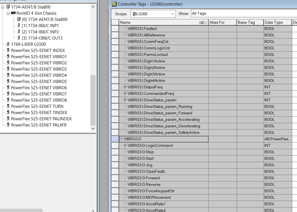
Now for the Comms signal: It is very common today for the VFD to be connected to the PLC via a communications link. For Allen-Bradley, this may be Ethernet/IP or DeviceNet/ControlNet, or for Siemens Profinet or Profibus. When this is done, discrete and analog information can be sent back and forth quickly and much more information that what is listed above can be exchanged. If the VFD and the PLC are the same brand, this is usually very easy to configure and UDTs can be used to map all of the drive signals. For different brands, eds (Allen-Bradley) or GSD (Siemens) files can be obtained from the drive manufacturer to add the device to the network. Of course with all of this information comes hundreds of lines of control code. Information like torque, bus voltage and current can be used for more precise control.
The encoder (or resolver) can also be connected to the load to provide positional or speed information. While this does not replace a servo system, precise position and speed control can be obtained for a system.
This next part is in answer to Moussa Guemdani in the Facebook group who asks (edited) “Using an HMI, when I choose a position and press a validate button the VFD starts and stops in the position given by an encoder. Vfd type : ABB”
As I mentioned previously, it is very difficult to answer this on a cell phone typing in Facebook, so I will try and elaborate here.
First, of course the encoder is connected to a high speed counter on the PLC. This allows for signals to be sent directly from the HSC card to the drive outside of the PLC scan if desired. Precise control can be obtained by monitoring the position via the encoder and ramping the drive speed down while approaching the target. When the position indicates it is almost at the target, the stop command can be given with a known ramp deceleration and the position should be very close. The problem here is, if you don’t slow down accurately, you can miss your target and have no way to creep small distances like with a servomotor. Also VFDs have no holding torque when at zero speed. So if possible, servo motors and drives should be used when more accuracy and speed are required. But I have achieved good results with VFDs in positional applications before.
I am not always sure what people are asking me for, especially if there is a language barrier. I am happy to answer questions when possible, and if the answer is complex I may post here on my blog as I have before. I have also done a lot of programming and systems integration in the past, and applications take a lot of time. Time is money, and right now I am pretty frantically trying to create income from my new office, mostly by creating training content. So Moussa giving me the drive brand (ABB) is farther than I will go in this post. Most VFDs have similar characteristics and connections, so what I have written still applies, but integration takes a lot of work and testing. And of course I have no where near enough information about his application, and am not anywhere near where he is.
I would advise anyone who has this type of application to do their best to SAFELY solve the problem, get the required hardware and hook it up, and spend some time with it. If you are careful, you shouldn’t break anything. If you need further help, by all means ask questions, but there is a point where you may have to get some expert help. Look around LOCALLY first, and see if there is a good resource that know what they are doing. Of course it will cost you something, but local is usually less expensive.
I hope this helps!

Electrical Engineer and business owner from the Nashville, Tennessee area. I also play music, Chess and Go.
It is very interesting..it helps me a lot of things when it comes to VFD in PLC control..thank you
Dear Frank
Thank you for your invaluable information.
I need your help in the following issue
I have a number of worm gears which is designated for crane movement (Industrial Automation). The movement is horizontal (axis X) and I need a motor drives which will be controlled by PLC system. I did not choose the drive yet, and I am making a rough estimation for the total number of digital & analogue inputs and outputs so I can proceed in selecting the proper PLC. I am considering 5 digital inputs, 5 digital outputs, 1 analogue input & 1 analogue output .
Do you think is OK, or I need more?
Thank you again
Depending on additional requirements that is probably enough I/O. For precise rotary positioning an encoder might also be needed which would require a High-Speed Counter card.