Are Things too Complicated?

Today’s post is inspired by an ongoing adventure I have been having in the design and fabrication of My Little Factory. For those who haven’t been following my post since the beginning of this year, a great deal of my time has been spent building out my training facility, the centerpiece of which is a tabletop demo that students will eventually be able to play around with. I started calling this “My Little Factory” after my April post of the same name.
Part of this little automation demo is a cleated conveyor that I am using to re-create an automation project I did about eleven years ago. Rather than using an indexer or servo to move the pockets consistently, the mechanical designer on the project decided to use a standard VFD (Variable Frequency Drive) and AC motor, along with some photoeyes to detect the position of the cleats. While this might have been a less expensive hardware option than a servo with encoder feedback, the amount of time that it took to make it work correctly more than ate up the savings. Anyway, one of the reasons I decided to re-create this method is that it illustrates some really good points and makes for a fun programming project for students. The basic concept is that the conveyor run signal is applied until the next cleat is detected with a sensor, the conveyor is stopped, and a second sensor is used to verify that the cleat (and therefore the pocket) is in the right position for operations.
When I started this tabletop project I purchased several different fiber-optic amplifiers both to use in this system as well as to help show students some of the wide range of features that photoeyes have. I bought a couple of Keyence amplifiers with all kinds of programmable windows and a set of (very expensive) convergent beam fibers, a couple of Banner’s newest amplifiers (shown above), and a variety of used stuff from EBay.
As I worked on different parts of this project I was always thinking about how I would mount the fiber heads to make them easily adjustable, which amplifiers I might use to illustrate which point, and various other details. Each section of this demo has its own purpose behind it, and once something has been done one way, it can be difficult and time consuming to change. So yesterday I finally got around to building the adjustable sensor mounts and testing the sensors. I decided to use the new Banner sensors partially because they looked really cool and partially because I didn’t have cables for the Keyence amplifiers (which look really cool too…)
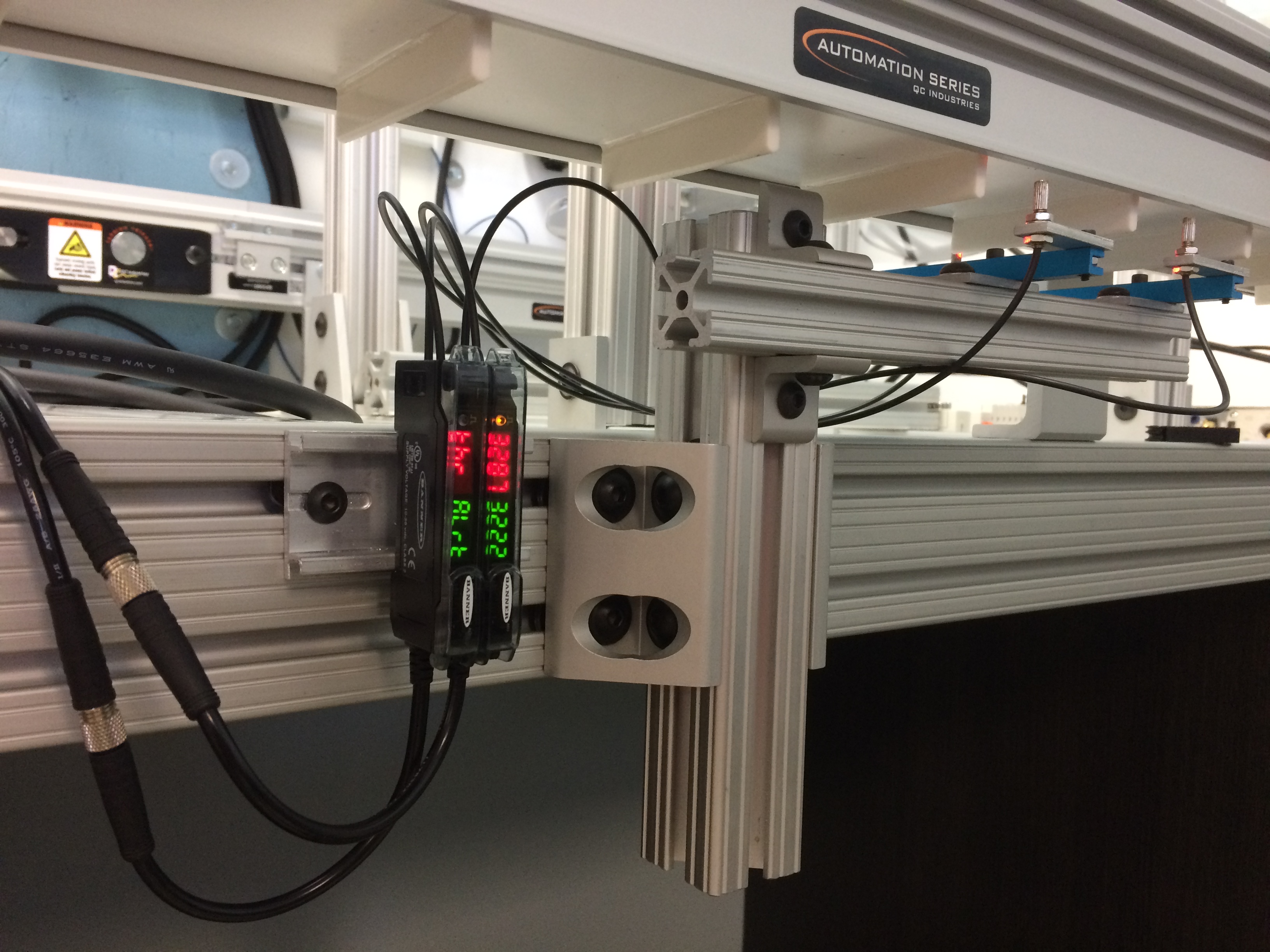
The mechanical mounting took longer than I thought it would. I had to make a lot of little brackets and drill/tap little pieces of aluminum, and then make do with whatever 80-20 extrusion pieces I had. Anyway I finally got everything mounted and powered on, and that’s when I was inspired to write this post. The instructions for the fiber amp is about 12 pages long! There are ways to program detection windows and tweak the timing, dynamically teach while the machine is running and set error thresholds, and change the response speed of the signal. What there didn’t seem to be was a simple on-off response to the cleat. As you can see in the picture, there is a number for the magnitude of the light signal and another for the setpoint. In addition the numbers will alternate with warning messages as shown in the leftmost amplifier. After getting it to operate yesterday before I went home, I took this picture this morning. The message “thr Alrt” was blinking, apparently meaning there was too MUCH light entering the receiving fiber. I know this because my green readout read 4000, the maximum magnitude for the amplifier.
Notice also that the fiber next to it has a yellow light at the top showing that it is ON. Not only did the fiber amplifier tell me that there was too much light, it also stopped working as far as I am concerned. When I misaligned the fiber heads a little bit bringing the magnitude down the amplifier output started operating correctly again.
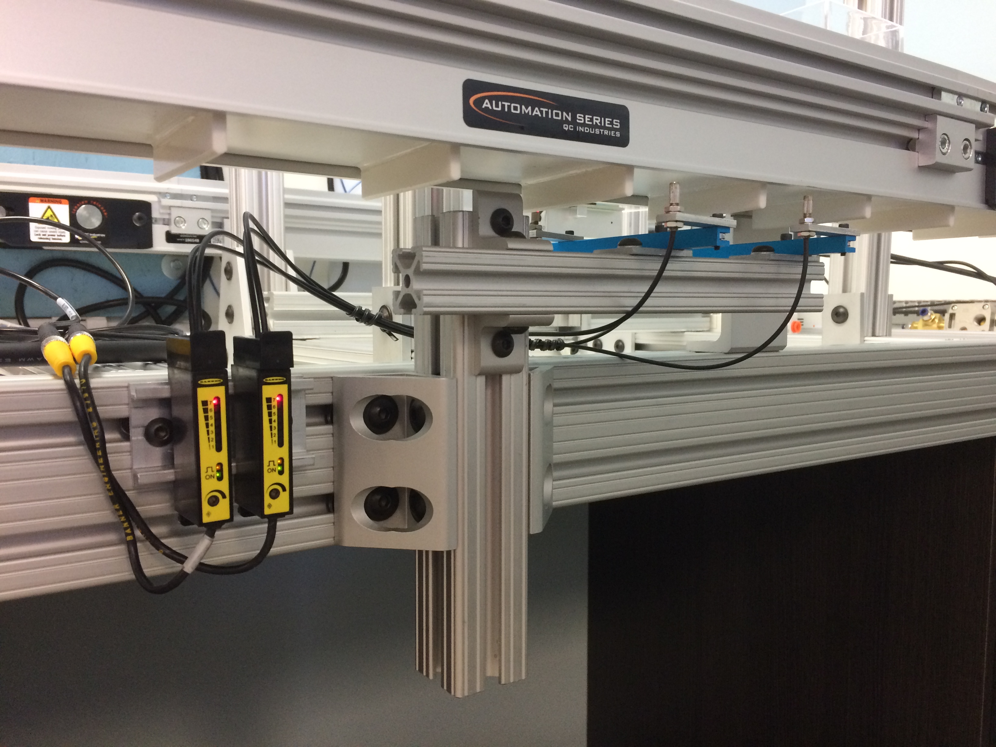
The end result of all of this fun was that I replaced the amplifiers with the two shown above. Though not as sexy looking, these are some of the used fiber amps that I bought on EBay. They have a simple bar graph showing how much light is being received and of course the same type of little yellow light showing that the output is energized. Instead of having six wires there are only four, and if you want it to operate Dark On instead of Light On you have to connect the white wire instead of the black one. It is however a much simpler device.

This picture shows my high-tech test device for checking the input to the PLC, blocking the beam with my finger. While there is no warning or remote teach wiring, this sensor will probably do the job. I say probably because the signal is apparently much faster on the newer amplifier.
When I started in the industrial automation field some twenty-odd years ago, systems were much simpler. Emergency Stop circuits were single channel affairs and PLCs were also much less complicated. Sensors were generally pretty basic also, although Omron used to have a really cool convergent beam sensor that actually physically changed the angle of the lenses. I haven’t seen anything like that for twenty years or so.
Anyway, my solution to the complexity of this new fiber amp was to replace it with one that took less time to set up and would still work even if I set it up wrong. I wonder how many other people have done the same thing when confronted with amazing new products.
What do you think? Are things getting too complicated?

Electrical Engineer and business owner from the Nashville, Tennessee area. I also play music, Chess and Go.