Ladder Logic 203: Faults
This is the third in a series of posts on Ladder Logic. So far I have discussed input and output routines and a bit on program organization. This week I am going to cover faults.
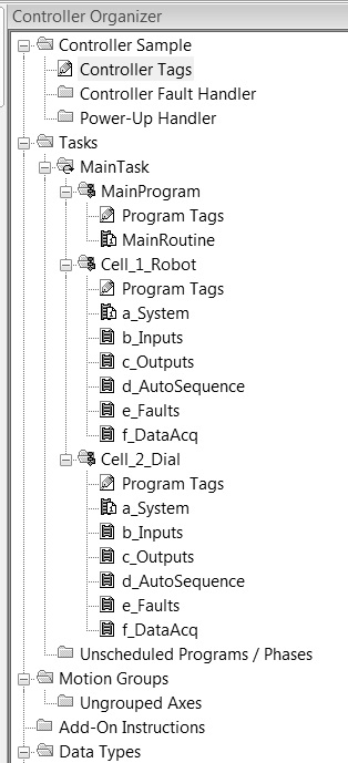
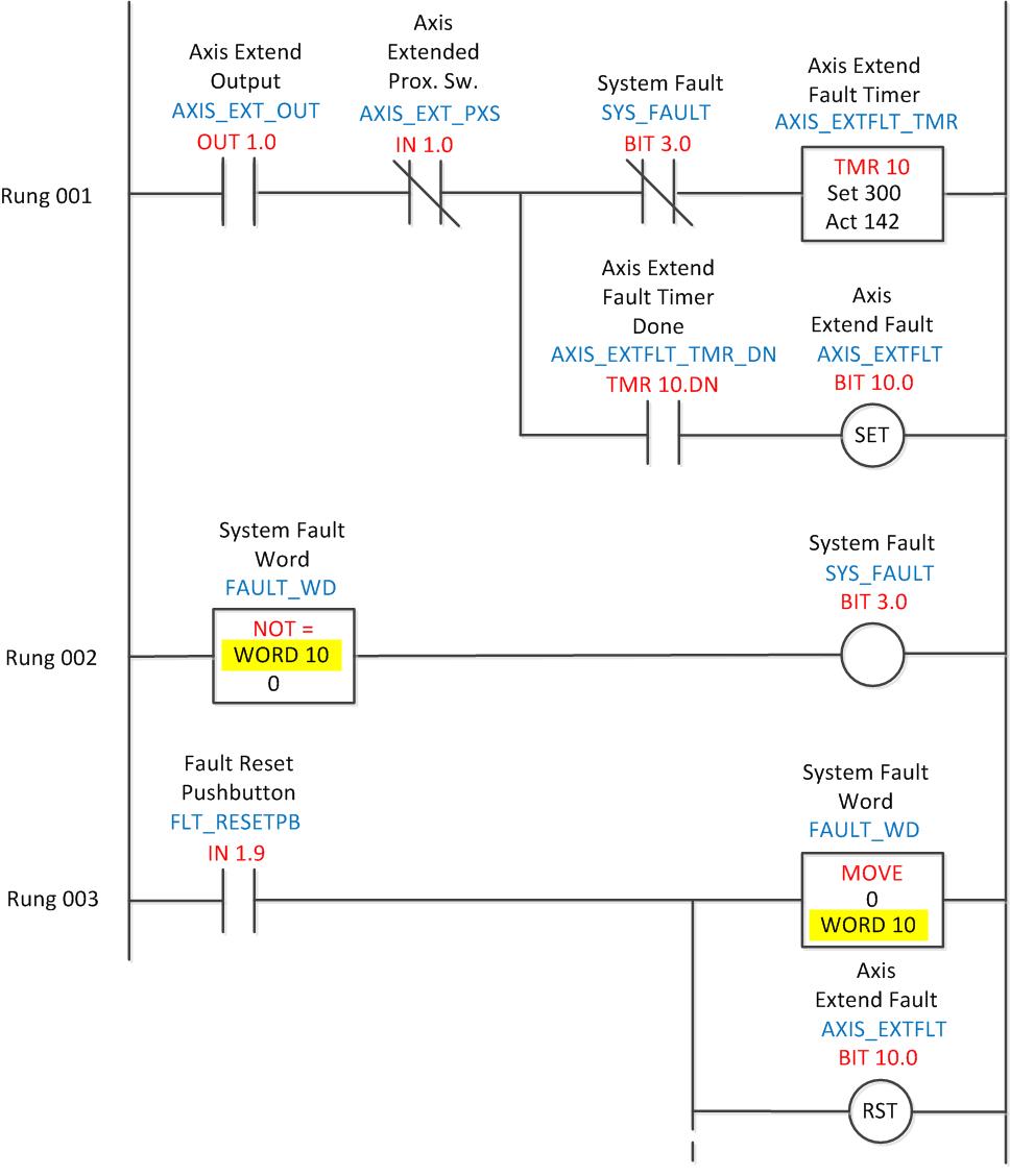
As shown in the organization chart on the left, each cell or station in a program will usually have its own fault routine. Faults are used to capture abnormal circumstances such as an actuator not completing its motion within a prescribed period of time (shown above). There is usually one fault for every motion (extend, retract, raise, lower and so on). Other faults may include lack of air pressure, emergency stop actuation, guard door switches and drive or overload alarms.
A few items of interest in the fault rungs shown above. Note that any system fault disables the timer on the fault rung. This serves a couple of purposes: 1. only the fault that happens first is enabled. This prevents subsequent faults that may have been caused by the initial fault from occurring. If air is removed from the system several pneumatic actuators may fault within the same event. 2. After the fault occurs the timer resets allowing a new countdown. This allows physical correction of the cause of the fault by maintenance or an operator.
The above rungs also show a couple of methods of resetting the fault. One is to clear the register word that contains the faults, in this case word 10. This fault word may be for only this cell allowing the system reset signal to reset faults in sections if desired; word 10 for cell 1, word 11 for cell 2, etc. Another method is to reset or unlatch faults individually. These reset signals can also be individually conditioned this way on each rung.
As shown in last week’s output routine, faults can be used in a permissive rung to prevent actuation of an axis. Fault bits are also used to activate messages on a touchscreen or HMI, for instance bit 10.0 might bring up a message that says “Axis SV1.0 Failed to Extend; Correct Fault and Press Reset”. The message would then be cleared when the fault is corrected and the fault reset button pressed.
In a post from last October on program organization I showed how some of these zones and cells work together, each having their own message lists, guard circuits and other subroutines. The organization list to the left also shows this. In my next post on system level logic I will discuss how the system routine in each cell relates to the overall machine-level system routine.
If you have some good programming tips please feel free to leave a comment!

Electrical Engineer and business owner from the Nashville, Tennessee area. I also play music, Chess and Go.
I have something similar to that, I have to come up with a fault logic to a bad insertion, that will cut on a red LED.