Fabricate – Panel Preparation
Today’s topic is on exactly what happens before you start wiring a control panel. It will also serve as an update on my progress on “My Little Factory”, which has drawn a lot of questions from my readers.
As I mentioned before, I don’t do a lot of panelbuilding, fabrication and wiring any more, most of my work now involves programming and training. In other words, old guy stuff. When I started the original Automation Consulting Services in 1996, much of our work was panelbuilding, and I learned a lot of the techniques as the company grew. Eventually most of the work was done by others, and my wife learned much more about it than I know. She ran the panel shop until we closed the business in 2006, then worked for two panel shops here in Nashville until a couple of years ago when she retired.
Anyway, with my new training facility I have dedicated the first part of this year to building things out, including this “Little Factory”. While my wife was kind enough to build and wire a couple of backplanes for me, most of the work is on me. So when I determined all of the components for my operator panel I decided to document the process of prepping the enclosure. Be prepared for a lot of pictures!
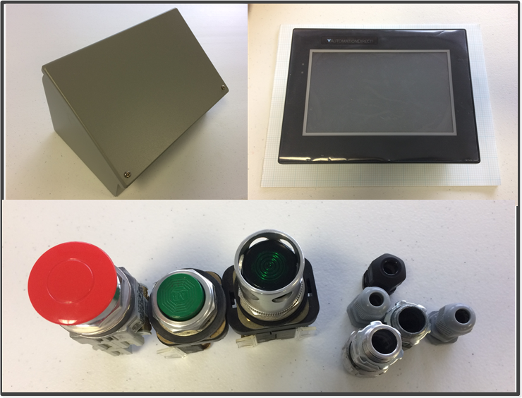
It all starts with figuring out what components you need in your panel or enclosure. In this case, since its purpose is to serve as an operator interface, I ordered a “consolet” type enclosure from Automation Direct. Many of the new components in my factory are ordered from them; they are easy to order from online and they ship for free in a day or two.
The Operator Interface itself is a “C-More” 7 inch diagonal touchscreen. I chose it because it is fairly inexpensive and has drivers for both Siemens S7 and Allen-Bradley. I’m not sure how it will talk to the Beckhoff 9020 PLC yet, but possibly Modbus or Ethernet IP.
The pushbuttons and fittings were a first guess at what I would use. I originally intended to use 3 buttons, but they didn’t fit so I used two. The green button serves two purposes: power on/reset for faults and the E-Stop circuit, and an index/cycle button for the cleated conveyor. The red button is of course an emergency stop. I have quite a few pushbuttons and pilot lights from old projects, so I just used those. I also had all of the fittings.
You can see the piece of graph paper underneath the touchscreen. After measuring the back of the HMI I used graph paper to outline the cutout.
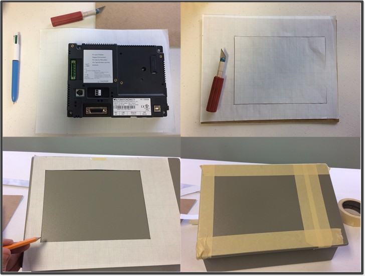
These pictures show the process of transferring the cutout size to the face of the consolet. If I were doing this professionally, I would create a CAD drawing of all of the surfaces of the consolet, measure all of the components and provide a formal drawing to my panelbuilder. Since I am doing everything, I can just “wing it”. I have a pretty good eye for things being straight, and the graph paper helps, so I didn’t have to do much actual measuring.
The ultimate goal is to get a taped outline of your cutout onto the surface you need to cut out. The tape is a cutting guide, and also serves to protect the surface from the saw.
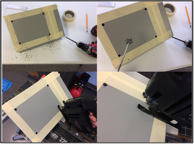
After taping the outline, I drilled holes in the four corners of the rectangle. The key here is to make sure that the holes don’t extend beyond the edge of the tape. I’ve found that a magnet is useful to pick up the big shavings from the drill. The holes should be big enough to allow the jigsaw blade to fit through them I also drilled small pilot holes before using the larger bit. The advantage of using a smaller jigsaw blade is that you can curve the cut slightly. The saw blade can then be run back and forth toward the corners of the rectangle to make the edges straight.
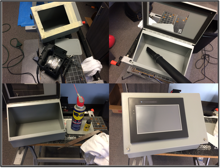
After finishing all of the cuts a magnet and vacuum cleaner was used to pick up all the loose metal. I used a flatt file to smooth all of the edges, removed all of the tape and cleaned the surfaces with WD-40 and “Goo-Gone”, the little bottle shown next to the open consolet. After that its good to check and ensure that the HMI fits in the hole, you’d hate to have to come back and file the opening any more!
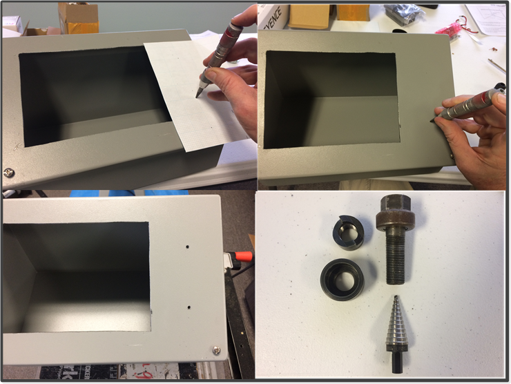
I used the same graph paper to mark where the pushbutton holes would be drilled. Notice that I had originally marked for three buttons, but I found that they wouldn’t all fit when I looked at the inside of the consolet. This is again where, for a serious design project, you would want to draw everything ahead of time.
The item shown in the next frame that I used to mark the holes is affectionately know as a “pinger”, the technical name would be a spring-loaded center punch. This item is also commonly used to mark screw holes on an enclosure backplane. After marking the centers I used a small drill to make pilot holes.
The pushbuttons are both 30mm in size, and I happen to still have my Greenlee punches for several different sizes. You can see in the next frame that I also have a stepper bit that is a good size for the shaft of the 30mm punch.
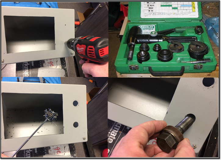
I then used the stepper bit to drill the holes larger so that the shaft of my knockout would fit through the hole. I also had a picture of my old hydraulic knockout kit which I sold when I closed my company in 2006. As you can see it had a lot of different sized punches in it and was much quicker to use. I’m glad I kept my old wrench driven set though. As you can see the magnet also came in handy again.
When using the punch it is important to put the items together correctly; stud through the hole in the die and then through the front of the hole in the panel, then thread the cutting die onto the back. I once had a guy who worked for me put the die on backwards and he snapped the stud right in two. This is surprisingly easy when using the hydraulic punch.
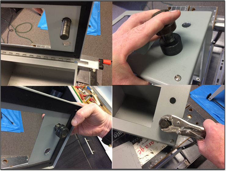
I like to use vise grips to turn the stud. That way I can let go of them and turn the panel, and they stay connected.
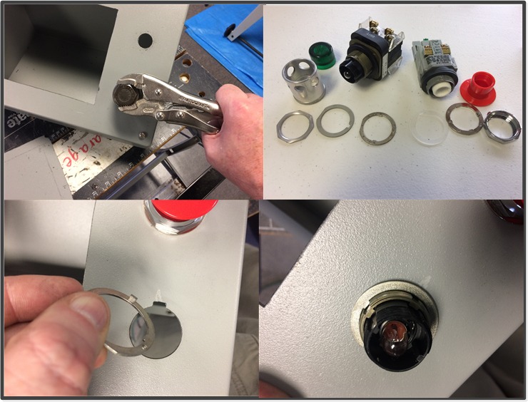
After about 12-15 full turns of the stud the hole is ready to notch. As you can see in these pictures, there is an anti-rotation ring around the body of the pushbutton. The little stub on the ring fits into a notch that stops the device from rotating within the hole. The best tool to put this notch in is called a “nibbler”. I have one but forgot to take a picture of it, I’m sure you can find a picture online. If not, e-mail me and I’ll send you a picture. You can see what the ring looks like installed.
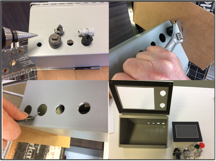
There are four fittings on the back of the consolet for cable entry. Two of then are 1/2″ fittings, which required another knockout, while two of them were drilled with a stepper bit. There are also three holes on the bottom used for mounting screws.
The tool shown in the lower left is known as a deburring tool. This is used to remove sharp edges from the holes. In the lower right you can then see the prepared consolet and associated components prior to assembly.
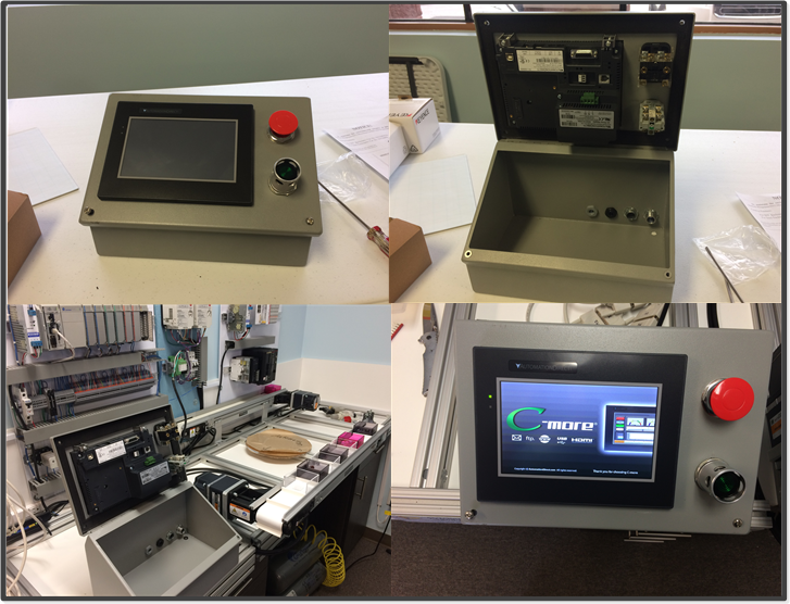
These pictures show the assembled consolet on a table, then bolted to the extrusion frame. After a bit of wiring there is the HMI powered up.

This picture is of the powered up consolet on the machine side of the frame. The picture below is of the left, or process side of the “Factory”.
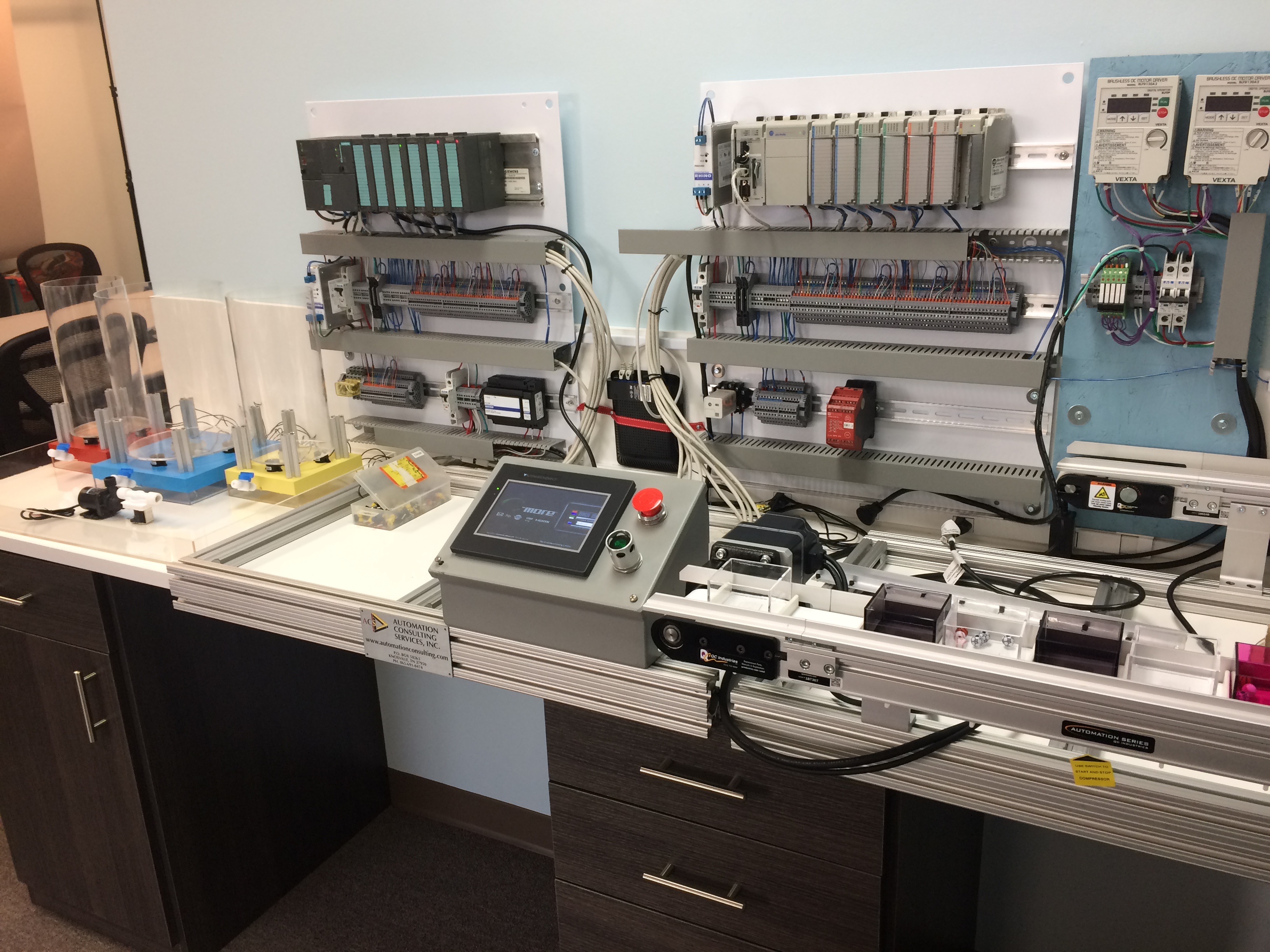
As you can see, some progress has been made, but there is a long way to go. The disc on the right side is the dial table, and as you can see I have painted and mounted the process tanks. I am still waiting in delivery of the pneumatic components for the pick and places and the SMC dial table mechanism. Part of the escapements have been made. I had mentioned possibly needing to use a machine shop to finish out the escapements; I may now be able to do it myself if I can get hold of some of the proper sized aluminum angle. More updates to follow next month.
By the way, I will be having an open house at my new facility toward the end of the week of June 5. If you are in the Nashville area, stop in and say hi! I will announce the actual date next week when I have finalized things.

Electrical Engineer and business owner from the Nashville, Tennessee area. I also play music, Chess and Go.