Ladder Logic 306a: Simulation
Today’s post relates to a new method I am using to teach some of my advanced classes. In a basic PLC training class, pushbuttons and pilot lights built into a trainer are used to complete exercises, usually in order to illustrate the use of different instructions on the PLC software platform. Advanced classes concentrate more on the techniques used in programming, such as Auto Sequences, Part Tracking, and other System functions.
Making all of the elements of a properly organized program operate together can be a daunting task. All of the different types of routines I have described in my previous PLC articles relate to each other, coils and Move instructions from one routine often drive contacts and comparison instructions in others. For contacts that represent the state of a machine or sequence they are easy enough to test; after all, things like Auto/Manual Mode, AutoCycle and even Faults are generally indicated by internal memory bits.
Inputs and outputs however are a different story. In a larger machine or system, they represent a lot of different types of sensors or output devices. With the trainers that are often used in training classes, you quickly run out of buttons, switches and pilot lights to substitute for your real world devices. Input devices such as buttons, switches and potentiometers also don’t react automatically in real-time to sequences and output commands.
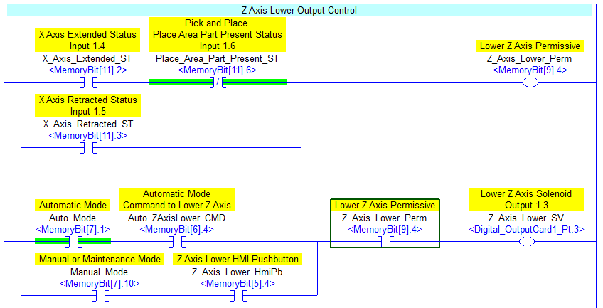
This is where a Simulation routine can be useful. The output logic shown above is similar to those I used in my Ladder Logic 202 article from several years ago. In this illustration, notice that the inputs and outputs are “aliased” to memory bits rather than real world I/O. If you are using a platform other than Allen-Bradley, don’t worry; the point is to uses internal memory rather than real inputs and outputs.
When the Z-Axis_Lower_SV output is activated in a real machine, the Z Axis Lowered sensor would usually be activated automatically. Since this is not a real solenoid valve driving an air cylinder with a sensor on it, we need to simulate the sensor being made.
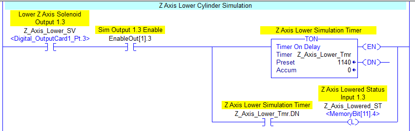
This timer circuit does the job nicely. Notice once again that a memory bit needs to be used to simulate the input. The input memory bits can then also be used in the auto sequence to step from one sequence state to the next. The EnableOut bit is used in case a Fault needs to be simulated. If the bit is disabled, it is as if the output activated but the input was never detected, the fault timer will then time out and latch a fault condition.
Also notice here that a “latch” or “set” bit is used for the input. This is especially important for solenoid valves that are turned off when the sequence proceeds to the next step. When the output goes off the simulated sensor will stay active.
It is best to put all of the simulation rungs in a separate routine. If the program is not just for training but for a real machine, the simulation routine can be removed or disabled later. Simulated I/O can also be replaced later with the real stuff.
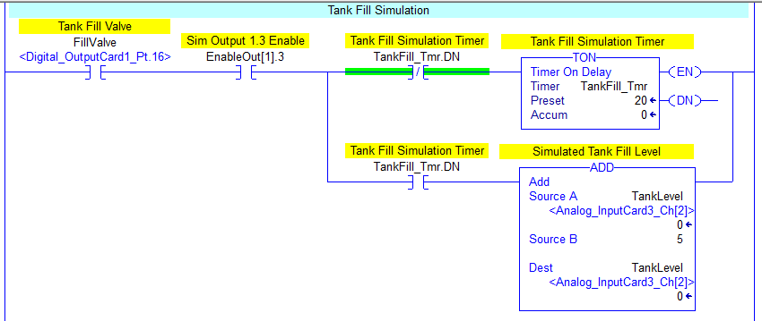
What about analog values? Once again, a timer is used for the simulation. In this case, the tank level will increment by five every twenty milliseconds. Both the timer value and the tank level addend can be adjusted to achieve the desired result. There is more conditioning that should be done to simulate a real tank, but this shows the general idea. To drain the tank, use a subtract instruction. This can be used to test PID instructions also.
I have started using this technique in some of my advanced classes. About a month ago I taught a class where we wrote a palletizing program. Students used pushbuttons and pilot lights for some of the I/O, but for sensors that we wanted to react automatically I showed students this technique and it worked quite well. Since real I/O is pretty limited on training equipment it also allowed for writing much larger programs.
Hopefully this will inspire you to use this technique when you need to test your program. Often real equipment is not available during the design phase of a project, this allows the programmer to test some of the more critical code before deploying it on a machine. With an HMI, it even allows for visualization of the process via animated objects.

Electrical Engineer and business owner from the Nashville, Tennessee area. I also play music, Chess and Go.
0 Comments on “Ladder Logic 306a: Simulation”