Circuit Breakers
Today’s post continues a series on electrical design that I started last week. Saravanan asked a question; “Thanks for the post. I want to learn about designing control circuits for motors. For example: How to select the breaker.. and also which area to focus as a design engineer. Kindly give me you valuable idea for me. Let me know if any book or website or doc are available.”
First, what is a circuit breaker? The following is from section 3.4.1 of my book:
A circuit breaker is a circuit protection device that can be reset after detection of an electrical fault. Like all circuit protection devices, its purpose is to remove power from an electrical device or group of devices, protecting the circuit from damage. Circuit breakers are rated by the current at which they are designed to trip, as well as the maximum current they can safely interrupt during a short circuit.
Circuit breakers interrupt a current automatically; this requires some kind of stored mechanical energy, such as a spring or an internal power source, to actuate a trip mechanism. Small breakers such as those used for branch circuit or component protection in a machine are usually self-contained inside a molded plastic case. Larger circuit breakers usually have a pilot device that senses a spike in current and operates a separate trip mechanism. Current is detected in several ways. Magnetic breakers route the current through an electromagnetic
circuit. As the current increases, the pulling force on a latch also increases, eventually letting the contacts open by spring action. Thermal magnetic circuit breakers use a bimetallic strip to detect longer-term over current conditions while using a magnetic circuit to respond instantly to large surges, such as a short circuit.
Circuit breakers usually have a reset lever to manually trip and reset the circuit. This is an advantage over using fuses, which must be replaced after one use. In industrial applications most circuit breakers are used for low-voltage application (under 1000 V). Medium-voltage (1000 to 72 k) and high-voltage (more than 72.5 kV) breakers are used
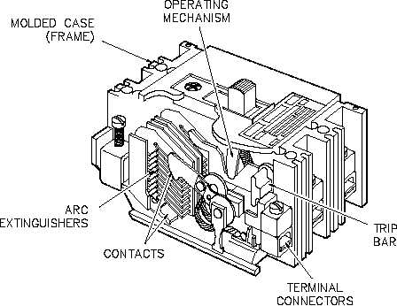
in switchgear applications but are rarely seen in industrial plants, though medium voltage switchgear is used in some process facilities. Low-voltage breakers may be of the DC or AC variety and generally fall into the categories of miniature circuit breakers (usually DIN rail mounted, up to 100 A) and molded case circuit breakers (self-contained, up to 2500 A). An example of a molded case breaker is shown at the top if this post.
Circuit breakers must carry the designed current load without overheating. They must also be able to withstand the arc that is generated when the electrical contacts are opened. Contacts are usually made of copper or a variety of alloys. Contact erosion occurs every time the contacts are opened under load; usually miniature circuit breakers are discarded when the contacts are worn, but some larger breakers have replaceable contacts.
There are two types of trip units in low-voltage circuit breakers: thermal magnetic and electronic. The thermal magnetic trip units contain a bimetallic thermal device that actuates the opening of the breaker with a delay depending on the overcurrent value. These are used for overload protection. The magnetic trip device has either a fixed or adjustable threshold that actuates the instantaneous trip of the breaker on a predetermined overcurrent value—usually a multiple of the overload current rating.
Electronic trip units use a microprocessor to process the current signal. Digital processing provides four different trip functions: the long and short time-delay trip functions per ANSI code 51 (AC time overcurrent), the instantaneous trip function per ANSI code 50 (instantaneous overcurrent), and the ground-fault trip function per ANSI code 51 N (AC time ground fault overcurrent).
Circuit breakers are categorized by their characteristic curves for different applications. Highly inductive loads, such as transformers, can have very high inrush currents of 10 to 20 times the current rating of the device. These are classified as a class “D” curve. Normal inductive loads, including most motors, have a current inrush rating
of 5 to 10 times the rating of the device and are classified as a class “C” curve. A class “B” curve is used for most lighter-duty non-inductive loads and has a rating of two to five times the circuit breaker rating.
Circuit breakers are also rated for use as branch, supplementary, or feeder devices. Feeder circuit breakers are generally of the molded case variety and are designed for main power feeds. They are typically tested at 20,000 A interrupting rating. Branch circuit protection is tested for at least 5000 A interrupting rating and is used for branch
circuits under the main breaker. Feeder and branch circuit breakers must be listed devices by Underwriters Laboratories (UL).
Supplementary protection devices are used for equipment protection in a branch circuit. They are classified as “recognized components” by UL rather than listed. They are tested with upstream branch circuit protection and are generally rated for 5000 A or less.
Motor circuit protectors (MCPs) are special application breakers with adjustable magnetic settings. They allow the operator to set the breaker’s magnetic protection level just above the inrush level of the motor. Overload protection for the motor is supplied in the starter’s overload relay. This combination allows protection of the motor without causing nuisance trips. MCPs are UL-recognized components.
Motor protector circuit breakers (MPCBs) are UL-listed circuit breakers with fixed magnetic protection and built-in motor overload protection. These breakers’ trip units are adjustable for Motor FLA ratings and can be set for overload trip class. MPCBs can be used directly with a contactor for a complete motor starting and protection package.
As I mentioned last week, vendor catalogs and manuals are an excellent resource for technical information on components. Many electrical distributors also have seminars or “lunch and learns” that cover the technical details of their products.
To properly select a breaker for an application, it is important to first understand exactly what the purpose of the breaker (or overload) is in the circuit. This allows the choices to be narrowed down to the type and class of breaker required. Only then can you use the sizing table for that particular type of breaker to make the actual selection. Another important detail to consider when selecting a breaker is, what brand does the customer prefer or specify? What kind of spare parts do they keep on the shelf? What is readily available from local vendors?
As you can see, there are a lot of considerations to take into account when selecting overload and circuit protection devices. This doesn’t even include the possible choice of using fuses instead (I will cover fuses next week). Hope this helps!

Electrical Engineer and business owner from the Nashville, Tennessee area. I also play music, Chess and Go.