Motor Control Design
Today’s topic is in response to Saravanan who posted a request last week on my “Panel Layout and Electrical Design” post of about a year ago. He asked “Thanks for the post. I want to learn about designing control circuits for motors. For example: How to select the breaker.. and also which area to focus as a design engineer. Kindly give me you valuable idea for me. Let me know if any book or website or doc are available.”
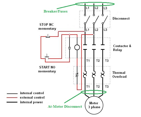
The diagram above shows a typical wiring diagram for a three phase motor starter. A motor starter consists of a contactor with a coil and an overload, typically thermal. The starter coil is available for various voltages, in the US the coil would typically be 24vdc or 120vac powered. The diagram above shows the power for the control circuit (pushbuttons and coil) being drawn from the L1 and L2 phases of the motor starter; coils are available for 240 and 480 volts, but I would typically not design a control circuit using such a high voltage. Some OEM companies who build compressors, winches etc. do this, but for safety I like to use lower voltage for all control circuits. If the circuit stands alone, a small control transformer can be used to step the control circuit voltage down to something safer like 24vac.
The overload is a device that senses if too much current is being used by the motor. If a motor stalls or windings become shorted, it will draw more current. This current may not be enough to trip a circuit breaker or blow a fuse, but nonetheless needs to be accounted for. A thermal overload uses bimetallic strips to sense the current in each motor phase. If too much current passes through the strip, it opens the overload contacts, which are wired in series with the motor. In addition an auxiliary NC (Normally Closed) contact is wired in series with the motor coil. This ensures that even after the motor has been disconnected through the overload and the heated strips have cooled and returned to their closed state, the overload must be manually reset to allow the coil to be energized again. In addition to the NC contact on the overload, a NO (Normally Open) contact is used to provide indication that the overload has tripped. This is typically wired into a PLC input or pilot light to alert a technician.
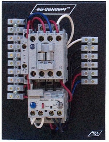
The picture above shows a motor starter with the overload wired into terminal strips. The four screw terminals at the bottom with the pairs of black and white wires are the NO and NC terminals. Note the features of the overload itself: the blue dial with the arrow is the trip setting for the overload. Overloads and contactors must be properly sized for the motor. The overload is sized for a range of currents; usually the trip point is set somewhere around 1.2x the full load current (FLA) of the motor.
The red button is used to test the overload by tripping it. It is then reset by pushing and turning the gray button on the right. The small black square is a little window with a flag to provide visual indication of the overload status.
Overloads usually take several seconds to trip. They are not meant to replace the short circuit protection (circuit breakers and fuses) of the circuit. Breakers and fuses trip or blow very quickly in the case of a short circuit. My next post will cover more on circuit breakers and fusing; this is a topic all by itself. The label in green in the diagram shows where the circuit protection is located before the starter.
The other green label at the bottom of the page shows where an “At Motor Disconnect” would be located. If a motor is located far away from the starter this is used so that a motor can be disconnected locally. This is very common on conveyor systems and pumps so that a motor can be safely replaced. Additional circuit protection may be placed here also.
Sizing of components (starters, circuit protection) is usually done using tables that specify devices based on the horsepower (or kW) rating of the motor. These tables are available online or in catalogs provided by the vendor. My book also has some handy tables in it for wire sizing and circuit protection along with further explanation of motor starters and variable frequency drives (VFDs). I also wrote a post on VFDs here two years ago.
There is a lot more information online about motor control design. One thing to take a look at is the wiring diagrams for a single-phase motor wired into a three-phase motor starter. It is important to ensure that motor wiring is passed through all three phases of the overload. Motor circuit design is not particularly difficult. Some of the best information can be obtained by visiting vendor websites or getting hold of a motor starter catalog or specification manual. Allen-Bradley, Siemens and Schneider’s websites and catalogs are a good start.
Hope this helps!

Electrical Engineer and business owner from the Nashville, Tennessee area. I also play music, Chess and Go.