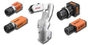
Vision Guided Robots

This week was my first experience using vision and robots together. I have integrated many vision systems in the past and also done a number of robotic applications but this was my first time using vision to guide the robot.
There are basically two different ways to tie the two together; mounting the camera on the robot’s end effector tooling so that wherever the tooling is, that is what the camera is looking at, and mounting the camera in a fixed position to look at the robot’s area of operation. The job I am currently working on has instances of both of these, but I am going to cover the setup for the fixed location instance today.
The first thing that has to be done is to place the two systems on the same coordinates. The robot in my case is at a 45 degree angle to the camera’s field of view, so the first thing I did was to change the robot’s workspace or frame reference. For this I used the camera’s calibration grid which is a printout of a checkerboard pattern with 20mm squares on it. The camera I am using is a Cognex Insight, not a PPT as shown in the above picture; the robot however is a Denso SCARA type.
The printout was placed in the approximate center of the camera’s field of view (FOV) so that the X axis of the pattern lined up with the camera pixels. The robot was then taught two points on the X Axis and entered into a “Work” variable which is called a frame in some other robot platforms. When this workspace is invoked the robot’s X-Y space is then referenced to this variable.
The camera was then used to capture the image and save it. Cognex has an algorithm for calibration that places cross-hairs at all of the intersections on the grid. One set is then chosen as the origin and the X and Y directions are defined from there. The robot is then used to locate the coordinates of the origin and the data is entered into the camera. After the grid spacing is entered the calibration algorithm is triggered and the camera can then report the location of objects within the FOV in real world robot X-Y coordinates.
Because objects at the edge of the FOV are farther from the lens a parallax is created where coordinates have to be slightly scaled, this is another feature of the Cognex system. This is common in vision applications where measurement data must be very accurate. In my current application the X and Y coordinates as well as the rotation of the target object are sent directly to the robot controller from the vision system, these values are then massaged slightly to create a pickup point for the robot. The Z value is a constant, however if had not been another camera could have been used to capture that position also.
Using a camera with a fixed field of view is fairly straightforward because the coordinates remain constant as does the focus. If the camera is mounted on the end effector tooling the coordinate system needs to follow the robots position and the focus may need to vary. This brings up an entirely different set of issues to be addressed. It is also common for the camera to be offset from the gripper tooling in both cartesian and rotational coordinates.
By the way, an update on my book status: I have not received my contract from McGraw-Hill yet, but after checking with them a week or so ago they assured me that we are still on track. Apparently it just takes a while. Since I am still doing a lot of editing on the basic information this is ok with me… I am not ready to send the chapters out for technical review yet anyway.

Co-ordinate transforms are one of the best robot features; another time they’re really handy is when you need to coordinate the robot’s end effector with a XY table in its own coordinate system.
Telecentric lenses have features, such as much parallax removal and constant magnification, that can really help when trying to perform precision measurements with machine vision. I haven’t need to use one yet.