The Basics: Analog and Digital
Now that I have an end in sight in regards to having my book published, I have been going back over various parts of the manuscript and doing some editing. I have already done this a few times to the point where much of what was posted originally on this site under “The Primer” has been modified extensively. This section is one of those, it covers some of the basic concepts of automation. I thought I’d post the rewritten version for review.

2.1 Analog and Digital
The most basic element of automation logic is its digital state. A switch or signal may only be on or off. This can be represented as a signal being a zero (off) or a one (on). There are many elements in an automation scheme that can be represented as a one or zero; the state of a switch or sensor, the state of a motor, valve or pilot light or even the state of a machine itself.
The state of many devices can not be so simply described. A motor can be described as being on or off, but it has other parameters such as its speed that can only be described numerically. For this purpose an analog representation of the value is used. Depending on the types of numbers that are used an analog value can be represented as an integer or a fractional number with a decimal point.
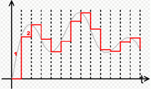
Analog input signals take the form of changes in either voltage or current. The analog device may be measuring position, speed, flow or another physical characteristic. These signals are connected to a circuit which then converts the signal into a digital number. Output analog signals also take the form of changes in voltage or current. A digital set point is converted to an analog output which may drive the speed of a motor or the position of a valve.
Analog inputs and outputs must go through these digital to analog and analog to digital conversions due to the inherently digital nature of computer and control systems. An analog value can have an infinite number of values within a given range; pick any two points along the constant slope of a voltage change and there can always be another point between them.
Electrical signals are converted to digital from analog inputs using an analog to digital converter circuit (ADC). Signals are converted from digital to analog using a DAC or digital to analog converter. These converter circuits are designed to operate over a fixed range of signals based on the application. The number of digital steps that an ADC or DAC is capable of is known as the resolution of the converter, this is described by the number of bits of the digital signal. A 16 bit DAC has a higher resolution than a 14 bit DAC, meaning it displays a higher number of subdivided values within its range.
Another specification related to analog signals is that of linearity. This is a definition relating to the “straightness” of the input signal or resultant conversion; linearity may relate to aspects of the signal being measured or to the converting device itself. It may be thought of as how much the converted signal deviates from the original.
______________________________________________________________________________
This is the article as it currently stands. There will still be quite a bit of editing on all of the sections of the book and no doubt the various technical reviewers will have lots of suggestions for improvement. If you see something in this section that needs changing or elaboration please let me know… there are of course many other sections of the book that reference this concept or elaborate on it such as 2.1.1 Scaling and various discussions on I/O, Sensors and Data. I appreciate any input or comments!
