Ladder Logic 204: Auto Sequences
Today’s post is a continuation of the series I started a few weeks ago on PLC programming in ladder logic. So far I have covered the topics of Inputs, Outputs and Faults; this topic does a lot to tie the previous topics together.
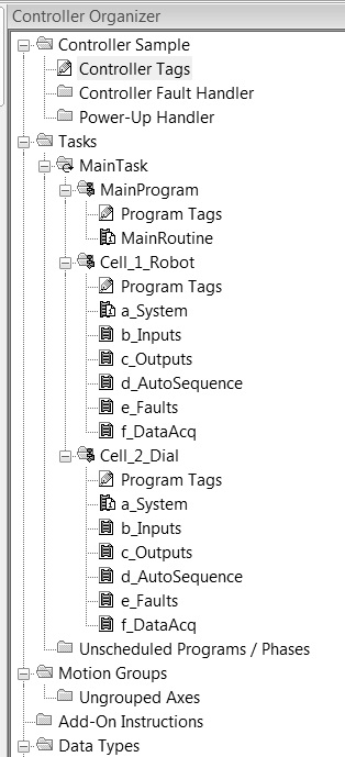 As with the other posts, this one uses the program organization shown to the left. The d_AutoSequence routine would contain this type of sequence and would use coils from the previously discussed b_Inputs and c_Outputs routines. Many of the system level coils such as modes will be discussed in a later post.
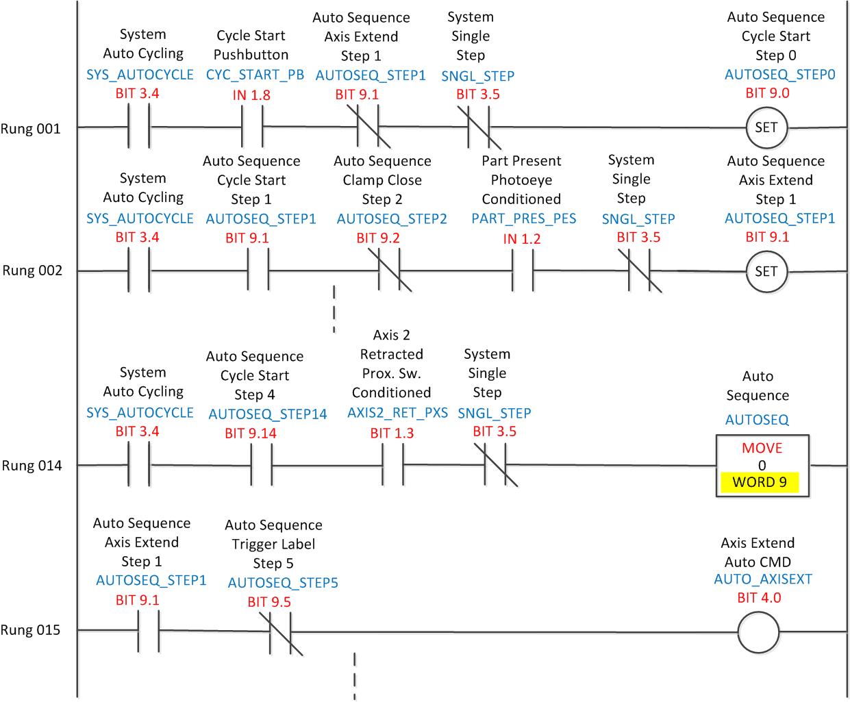
The sequence shown at the top of this article is a bit-based sequence. The idea behind using bits of a word is that the entire word can be cleared as shown in rung 14 after the sequence has been completed. At the beginning of the sequence the entire sequence word is assumed to have been cleared, resetting or unlatching all of the bits in word 9. This word is known as the sequence word and all of the bits within it are called steps.
The sequence word is no different than any other word in the PLC, it has simply been chosen as the address for the sequence. For PLCs with double integer registers this address could have 32 bits in it, for integers it would have 16 bits or steps.
At the start of the sequence all of the bits are in their off state. When the system is placed in Auto Mode the Auto Cycling bit can be started using some set of conditions, this may include a cycle start button or other cycle initiation method. In this particular sequence the cycle start button is also used to set the first sequence bit. There is nothing wrong with using it for both purposes, the SYS_AUTOCYCLE bit would likely be conditioned with other bits such as no faults, light curtain clear etc. This bit would most likely be set in the a_System routine of the program organization chart. Placing the machine in Manual Mode, a system level fault or a cycle stop are examples of situations that might cause the SYS_AUTOCYCLE bit to be reset. If this bit were reset the sequence would then maintain whatever state it was in until relatching the bit, which would allow the sequence to continue.
After the Cycle Start pushbutton has been pressed the sequence would be in its first state waiting for the part present photoeye to be triggered. Note that this is a conditioned bit as discussed in the previous Inputs post. This means that the eye would have to be blocked for 100 milliseconds before the bit is true. This is probably at least five or six scans of the PLC. When the bit becomes true the next bit in the sequence, 9.1 would be latched.
Note that the last rung in the top picture states that if bit 9.1 is on that the Axis Extend Auto CMD (command) will be on. If you look at the Outputs diagram from a few weeks ago you will notice that this was the bit used to activate the Axis Extend output bit 1.0 if in Auto Mode. This is the physical output from the PLC that drives the air valve. The Axis Extend Auto CMD bit is on in steps 1-4, if sequence bit 9.5 is on the Auto CMD bit is no longer true.
A typical next step in the sequence setting bit 9.2 might include the Axis Extend conditioned input (Bit 1.0 in the b_Inputs subroutine) advancing the sequence. The auto sequence would continue in this manner using as many steps as necessary before resetting the sequence as shown in rung 14. Although only one d_AutoSequence routine is shown in each of the cells, it is not uncommon to have several in each cell. There can even be a master sequence which consists of steps completed by other sequences. In this case the sequences might have names like d1_AutoSeq_PickAndPlace or d2_AutoSeq_DialIndex. Note the alphabetization of the subroutine names in the cells. This is a technique that can help in the organization and readability of the program, it is not necessarily the order in which the routines are called. More on this subject will be covered later.
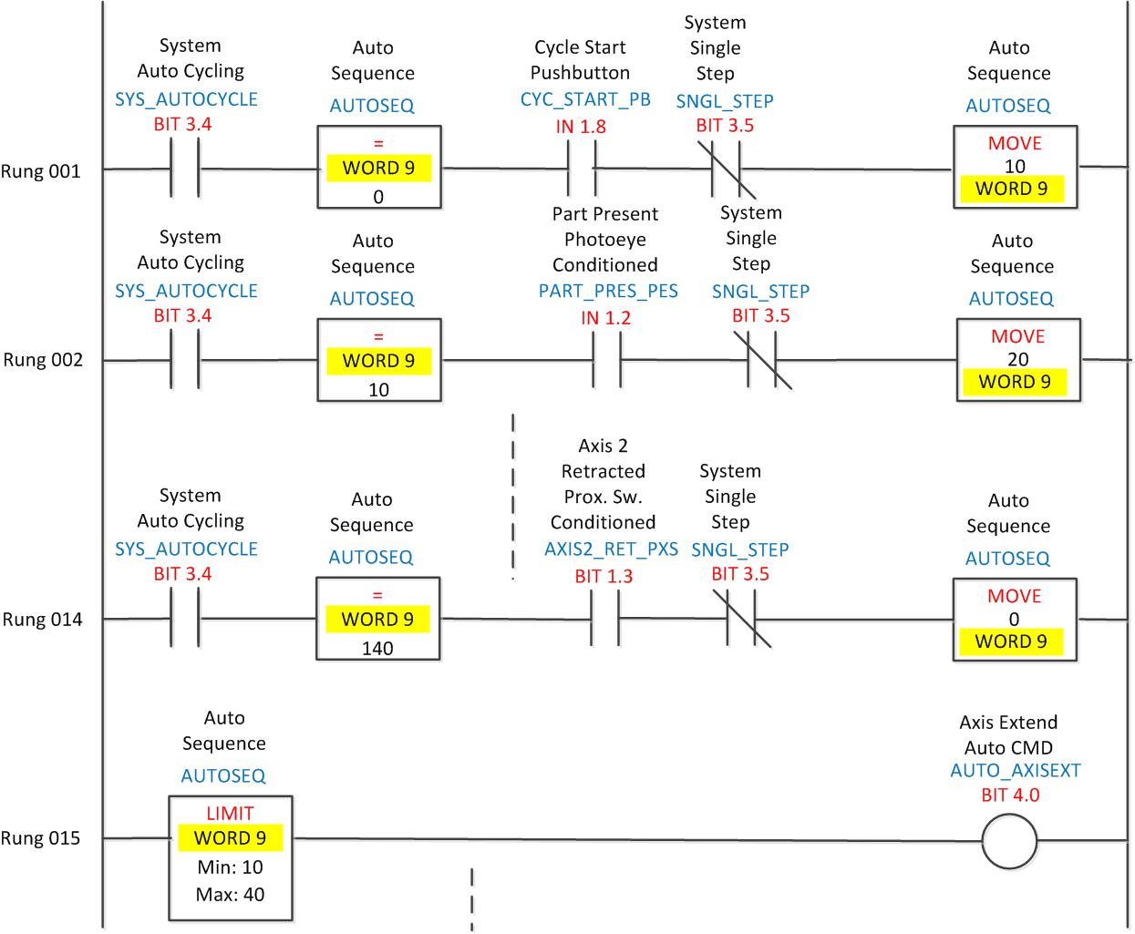
The sequence shown above is another type of auto sequence known as a numerical sequence. This sequence operates in much the same way as the bit sequence, but there are advantages and disadvantages to each.
Note that in the numerical sequence the values increment by ten; they could just as easily increment by 100. This makes it easy to later insert steps between existing steps without having to go back and change bit addresses that drive the CMD bits. With a bit sequence, though it is possible to leave spare bits for future modification there are simply not as many available steps in the word. The numerical sequence uses this technique much as a BASIC language programmer might have line numbers that proceed as 100, 200, 300 for ease of future modification.
Another important difference is that a numerical sequence can only have one number in it at a time. A bit sequence can latch and unlatch bits at will and can sometimes be more flexible, though typically this is not often done. They usually progress in sequential order.
I have used both types of sequencers in the past for different reasons. Most of the time lately I use bit sequences for typical auto sequence programming and numerical sequences for robot routines.
What kind of sequencers do you use?

Electrical Engineer and business owner from the Nashville, Tennessee area. I also play music, Chess and Go.
Hey… Thanks for taking the time to create this resource on the web! Your site provides some of the best details on real world applications of PLC programming I’ve seen so far.
I’m still really new to the field and have yet to create my own program from scratch (currently maintain other programs that have already been written). For creating a new program, I’m stuck on organization of the logical layout as compared to the physical layout of the machine. In other posts, you talk of having a hierarchy of Machine > Zone > Cells… and in one of your Automation Cycle posts, you suggest that a single Cell can have multiple Work Cycles (ie. Part Load, Process1, Process2, Unload, ect)… In the ladder layout pictured on this post, would u consider the Main Program to be at the Zone Level or the Machine level? Do you know of any examples on the web that show how these different labels can be applied to a machine (ie a machine layout with each area labeled as Zone > Cell > Work Cycle)?
all industries related basic level laader programs lik generator motor servomechnism etc
I am looking for a ladder diagram, 1 motor 2 contactors fast/slow, auto control where the motor runs for 2 mins in slow, when timed out the motor runs fast for 5 mins. manual control, when motor can be started in either fast or slow & latches in until the timer times out, also need the motor to run fast in inch mode when the 2 inch buttons are pressed, can anyone assist please.
Hi Dave, sounds fairly straightforward. If no one else replies I’ll write it up for my next blog post Sunday (7/5/15). What type of PLC are you using?
hi how can plc to PLC communication take place in auto cycle please send me in deatil