Ladder Logic 104: Memory Organization

One of the first decisions that needs to be made when designing a PLC system is memory allocation and organization. In the early years of the PLC memory came at a premium… 1K (one kilobyte) of memory for the program and data may have been all that was available for the programmer to use in a particular PLC. It was not unusual for programmers to assign unused I/O memory as data registers if the program grew to where the rest of the data registers had been assigned.
Memory allocation varies from platform to platform. All platforms have input and output (I/O) memory; this is because rather than accessing I/O directly, programs read the inputs at the beginning of the scan, writing them to a memory table. The program then processes the logic, using the saved input values and updating memory and the output table. At the end of the scan the output table is written to the physical outputs. A quick note here: a couple of years ago I wrote a post called “Ladder Logic 206: Scanning“. This post did not address how PLCs actually scan, rather it discussed the order in which routines should be placed. I plan to rectify that in a 100-level post soon. In general however, the statement above covers the mechanics of how the scan works.
I/O memory is assigned and labeled in different ways. For this post, I am going to use my three favorite platforms as an example.
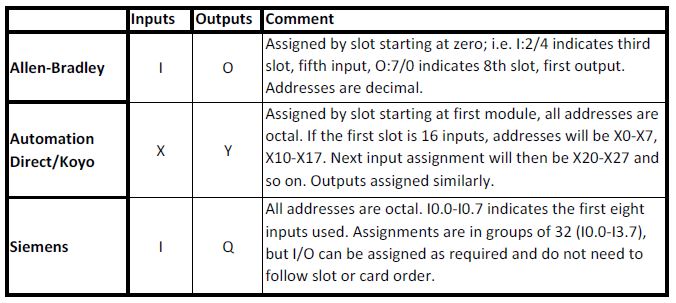
As you can see, the letter designators for I/O differ as do the way they are assigned to physical points. This is even further complicated by the fact that for Siemens, analog I/O starts at different points depending on the platform (example: PIW256 or PIW800 designates Process Input Word.) Allen-Bradley still follows the slot number, (i.e. I:6.0) while Automation Direct’s Koyo platform uses V-Memory locations for analog, i.e. V7630-V7633 may hold four analog values from an I/O card.
Timers and counters also need to have memory assigned to them. Since they have special data types such as presets, accumulated values and “done” bits, they are generally assigned special areas reserved for them. T0 or C2 (Siemens) or CT5 (Koyo) are examples. Allen-Bradley has registers pre-assigned for timers and counters, T4 and C5. Examples of AB addresses for these might be T4:1 or C5:3. These are then appended with /DN for the “done” bit or .pre for a preset value.
Allen-Bradley also pre-assigns registers for bits (B3), integers (N7) and REALs (F8). New registers can be opened up as required for timers, counters, bits, integers, REALs or floating point values, and strings. Examples might look like N14, B33, F27, T88 and so on.
For both Siemens and Koyo special areas are assigned for discrete bits. Siemens uses M bits or words for general programming use; bits may have addresses such as M10.2 while words, double words and bytes may be assigned as MW42, MD60 or MB16. Floating point values are placed in double word locations.
Koyo’s control relays are discrete only and use the designation “C”. They are also octal, and have addresses such as C10 or C217.
All of Koyo’s addresses, even the I/O, is overlaid with the “V” designation. V0 starts with timer current values, I/O may land somewhere in the V40000 range, while user data words of the volatile (non-retentive) and non-volatile (retentive) types fall somewhere in between. This can be somewhat confusing since even the system parameters are also located here. Locations also vary across the 200, 300 and 400 platforms.
Siemens PLCs also allow data to be organized into Data Blocks (DBs). These are structured by the programmer and can contain mixed data types. Most memory usage is placed here rather than in the “M” or marker memory. This allows for more application specific data organization. User-Defined Types (UDTs) can be used to further define data.
The previous descriptions apply to the older original platforms for these three types of PLCs. For Allen-Bradley this includes the PLC5, SLC500 and Micrologix families. For Automation Direct/Koyo, it covers the 200, 300 and 400 families and for Siemens the S5 and S7 series, 200, 300 and 400s.
All three of these companies also have newer tag-based systems. For Allen-Bradley the ControlLogix and CompactLogix platforms allow users to add memory in the form of tags, or text-based addresses that are added as needed. Since these are readable by the programmer and usually descriptive, tag-based programming allows programs to be uploaded and read easier without the requirement of descriptions.
Siemens TIA Portal platform is tag-based, however it is still important to have the program since data structures are not as easily correlated when uploaded. The S7-1200 and S7-1500 are Siemens’ tag-based PLCs.
Koyo’s Productivity 3000 platform is their tag-based PLC. As I mentioned in my post on Automation Direct, I do not yet have experience on this PLC, but I hope to get the opportunity to work with it someday. Tag-based programming is more efficient than the previously mentioned register-based systems and much easier to organize.
All of the previously mentioned platforms also allow for import and export of tags or descriptions by address. This enables programmers to manage and organize memory in an efficient way using Microsoft Excel, which I have emphasized in the past.
As you can tell, planning your memory usage and assignment before starting to program is useful and can save a lot of time.
For more articles in this series on PLCs and programming, check out the PLC tab at the top of this page. If you have something to add, please leave a comment!

Electrical Engineer and business owner from the Nashville, Tennessee area. I also play music, Chess and Go.
Excellent post. One of the reasons why the direction is important is because this is the way to communicate with the HMI. Here I give two complementary links
http://controlreal.com/en/plc-my-first-steps-2/
http://controlreal.com/en/memory-and-scan-cycle/