Ladder Logic 202: Outputs
This is a continuation of a series on programming techniques that I started last week. In the Ladder Logic 201 post I discussed conditioning, backchecking and debouncing of inputs. This weeks topic covers how outputs are actuated including permissives, Auto, Manual and Homing drivers. As with last week’s diagram, the black text represents the commented ladder element, the red text represents the address, while the blue represents the symbol or tag.
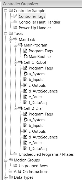
The diagram on the left shows the organization of a sample program. The input or output rungs shown in both this week’s and last week’s post might be in any cell, they are shown as b_Inputs and c_Outputs in the organization tree. Some programmers like to put all of their input and output rungs in a single subroutine rather than separating them by cell or station, but for longer programs with lots of safety zones or hundreds of I/O I like to separate them. This doesn’t mean that its wrong to put all of the I/O in one set of subroutines, indeed it might be better for small programs. The main purpose is to make it easy to locate.
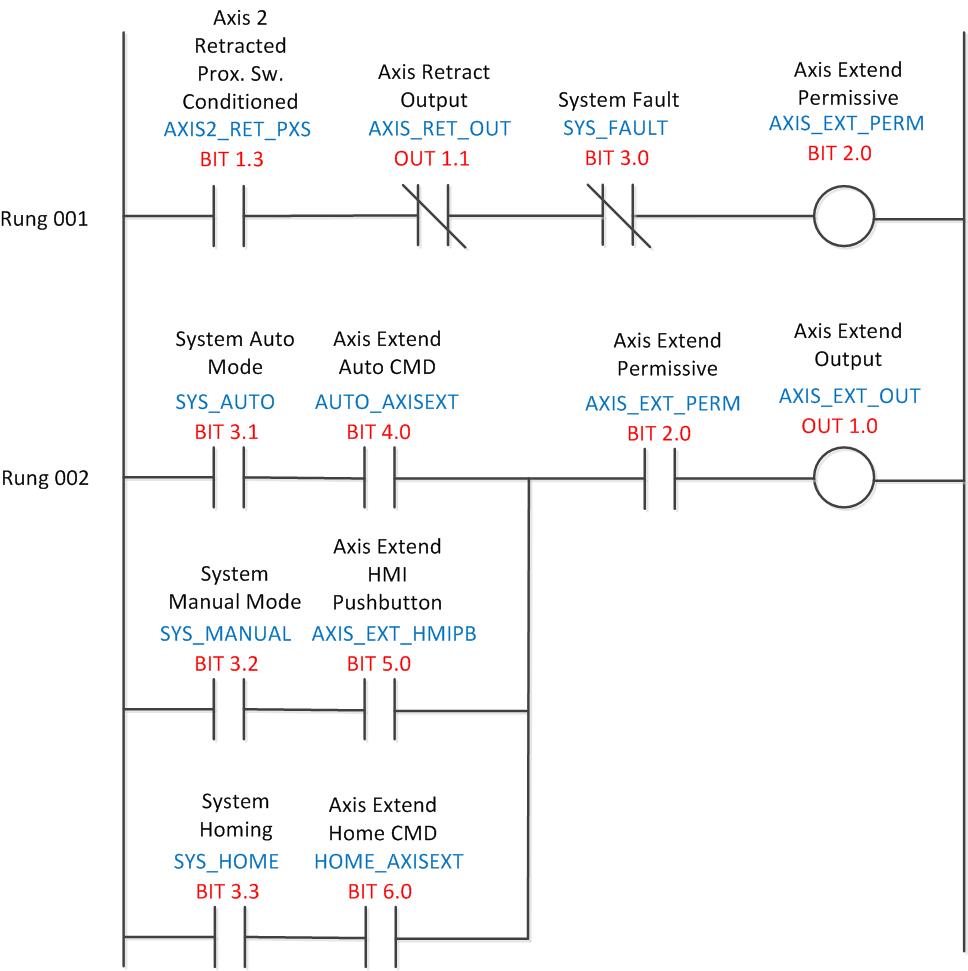
The permissive rung at the top of the diagram illustrates situations in which you might not want the actuator to be able to move. The first contact says that a hypothetical axis 2 actuator must be in the retracted position to actuate this axis. This is common when actuators might be able to hit each other. The second normally closed (NC) contact says that the retract output may not be on at the same time as the extend output, again a common practice. The third system fault contact states that the actuator may not move if there is a fault present. Faults will be covered in next weeks post.
The output rung is shown in rung 002. Note that the permissive contact must be on for the output to be activated. This rung assumes that the output is connected to something like a pneumatic or hydraulic double-acting solenoid valve. If the actuator is already at the extended position turning off the output will not make the actuator retract, it will remain in position. In the case of a system fault, air might be exhausted from the system, sometimes known as an “air dump”. In the case of a vertical axis care must be taken to ensure that the actuator remains in position when gravity takes over, often by means of a shot pin, piloted air valve or use of a closed center valve which will trap the air. Hydraulic systems don’t have this problem.
The top branch of the rung illustrates that when the machine is in automatic mode the output will be actuated by a coil from the auto sequence subroutine. This will be covered in a later post. Typically this coil will be active during specified steps of the auto sequence, generally I like to keep the output coils for these commands immediately following the sequence in the same routine. There will also usually be a rung comment describing when the Auto Command (CMD) is true.
The second branch shows that when the machine is in manual operation an HMI pushbutton will activate the output. This might also be a physical pushbutton on an operator console. The third branch shows a contact driven from a homing routine. Homing a cell or station is a common procedure used to ensure that all axes are placed in their proper starting positions. It is also common to have a separate homing sequence in each cell, this might be placed in the routine list as “g_Homing” if desired.
Notice also the bit selection in the ladder diagram. Bits 1.0-1.x are used for the conditioned inputs discussed last week. Bit 2.0 is used as a permissive bit, bits 2.1-2.x might be reserved for more permissives. Bits 3.0-3,3 are used for system level bits such as faults, modes and machine states, other 3.x bits might be reserved for similar conditions. The 4.x bits are used for auto commands, the 5.x bits are used for HMI pushbuttons and the 6.x bits are used for home routine commands. As you can see, organization of the program is important. I usually decide which bit ranges I will be using before starting to program. An Excel spreadsheet is a great way to do this.
As with the input rungs, it is a good idea to place the rungs in order of the output addresses. When organizing the PLC I/O it is also good to assign addresses according to a system; I generally assign actuators in the approximate order that product flows through the system.
If you have any other suggestions or tips feel free to leave a comment!

Electrical Engineer and business owner from the Nashville, Tennessee area. I also play music, Chess and Go.
please , I want help to use PLC as Analog to digital converter and link it with oscilloscope to see the shape of the digital signals.
I want to change the analog signals ( continually changed)to digital signals for communication purposes through internet .
best wishes
I use mainly RSLogix 5000 and am not familiar with the permissive and conditional bits. Can you please explain these?
Thank you.
Hi Deb, sure, no problem. As you can see in the diagram, there are several bits in the 1st rung that would prevent the output from activating even if the driving logic in the output rung below was true. For instance, there would never be a reason to activate both extend and retract logic at the same time on an actuator’s valve. If an Auto Mode command was active and extending a cylinder, the retract output couldn’t fire the opposite side of the valve and vice-versa. A fault might also prevent such an event. By consolidating all of these conditions in a single “permissive” bit there is a single rung where you can modify these conditions. The word “permissive” and conditional simply describes this, buzzwords if you will.
Program organization is up to the individual “artist”; there is no fixed or even best way to write a program. This is just one of many methods. It happens to be part of a standard that the machine builder I used to work for used. There are many other methods. With the relatively huge memory of the ControlLogix separating more complex rungs into these types of elements can make programs easier to read. Hope this helps!
Sorry for commenting on an old post. I love the idea of permissive rungs, but I have a question about the logic presented in Rung 001. If, as you discussed, the prox switches are tied to the extend and retract positions of a pneumatic actuator wouldn’t this rung turn off during the transient period when the actuator is in motion? In a pneumatic cylinder the retract and extend positions are generally defined by the extreme positions of the magnetic piston. During extension the retract prox (Bit 1.3) would turn off, turning off the extend permissive (Bit 2.0), and subsequently interrupting the Axis Extend Output (OUT 1.0) in Rung 002. The actuator would never be allowed to reach full extension. I’m relatively new to programming, so I apologize if I’m missing something obvious. Is there a clean way to account for this? This site has been of immense value in my efforts to learn the controls side of automation. Thank You!
Hi Keith, thanks for the question! Yes, of course the proxes’ status bits turn off during the transition, just as the the proxes themselves do. They are meant to act exactly as the prox itself does UNLESS somehow both proxes are made at the same time, in which case the status bit doesn’t turn on. That’s why this is called backchecking; it creates a fault if both proxes get made as well as if the prox in question doesn’t make when the cylinder is extended. It is effective only in the fault routine, whether running a typical jam timer on the cylinder output or if timing a sequence step. It allows both sensors to be checked during every move. Other wise sensors stuck in the ON position would never create faults.
As far as the permissives: The first permissive, Axis 2 Retracted Status, ensures that a different cylinder (assumed to be able to interfere with this cylinder) is, and stays, retracted. It uses the status bit described above as shown in the Input discussion, LL201. The second, the Axis Retract output, ensures that both the extend and retract outputs can’t be on simultaneously. The third, a general fault, is not always used here, but prevents the movement from initiating if a fault is present. It is optional.
All permissives need to be evaluated carefully. The main purpose to me is to prevent damage to actuators or safety, but there may be other cases. For instance, I rarely put the system fault in my permissives, other parts of the system often deactivate the output anyway, such as an air dump or going out of AutoCycle due to a fault. Thanks for the comment again!
Thanks for replying! I don’t think I connected that Rung 001 (LL202) is for Axis 2, while OUT 1.0 (Rung 002) is the output for a different Axis. This makes complete sense if Axis 2 needs to be parked while Axis 1 (or other) is in motion.