Ladder Logic 201: Inputs
*Note: Since the time of this post I have written a number of other posts on ladder logic you may find useful. These are listed below for your convenience:
Ladder Logic 101: Where do I Start? (February 2011)
Ladder Logic 102: Organization (October 2012)
Ladder Logic 201: Inputs (March 2013)
Ladder Logic 202: Outputs (April 2013)
Ladder Logic 203: Faults (April 2013)
Ladder Logic 204: Auto Sequences (April 2013)
Ladder Logic 205: System Routine 1 (May 2013)
Ladder Logic 206: Scanning (May 2013)
There are also a number of other PLC related posts if you look around on the site.
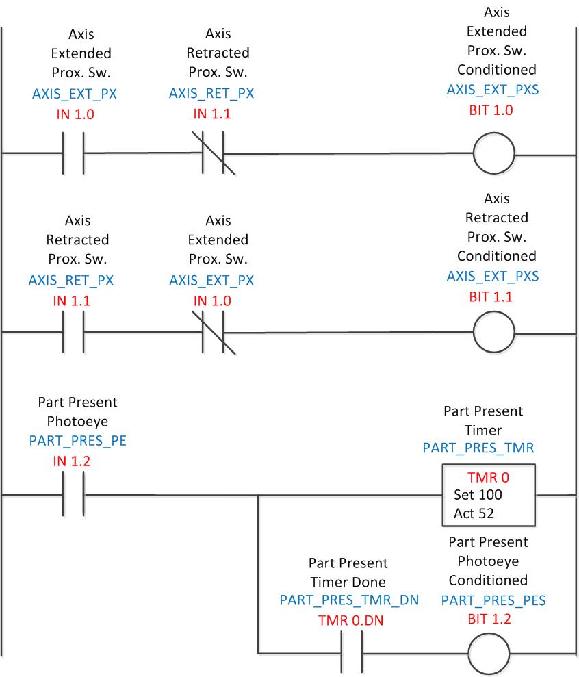
I have thought for a while about how to present some programming information that goes beyond some of the introductory stuff I have seen presented online. The problem as has been mentioned here before is how to present the information in a way that is not specific to any particular PLC platform. The picture above is the method I have decided to use. The black text represents the commented ladder element, the red text represents the address, while the blue represents the symbol or tag.
Todays topic is that of inputs. I discussed a little bit about program organization in a previous post, but in the next series of “200 level” topics I am going to be more program specific.
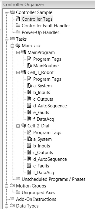 The picture on the left shows a couple of workstation”Cells” or routines. Each of these have several subroutines listed underneath them. A cell represents a station or group of mechanisms that constitute a discrete part of a machine, such as a robot, dial, pick and place and so on.
By inserting the a, b, c prepend to the subroutine name it can be alphabetized in case sorting is needed. I often use an Excel spreadsheet to organize and even generate PLC code.
The b_Inputs subroutine is where inputs are conditioned. In the above example an extend and retract sensor are placed in series so that if one of the sensors malfunctions it can be detected in a fault rung; both sensors should never be able to be on at the same time. The fault rung for detecting this condition will be covered in a future post. This technique is sometimes called “back-checking” the sensor. This is usually done for all extend and retract pairs.
The photoeye rung illustrates use of a timer to ensure that a part is not indicated until the eye has been blocked for at least 100 milliseconds. This is sometimes called “debouncing”, it ensures that a moving part has enough time to either reach an end stop or to ignore possible transient signals. It is not necessary to use this for every photoeye.
The conditioned bits are then used in the rest of the program instead of using the I/O address directly.
The input subroutine is also where I/O may be mapped from robots or other device. Scaling of analog inputs is also generally done in this routine.
It is generally a good idea to put the rungs in the order of the input addresses. This allows them to be located easily.
While browsing the PLC programming tutorials available online I found that almost all of them were specific to a brand. To learn the basics of whatever software you are using I would suggest checking out the tutorials available on these sites. Most examples seem to be for Siemens and Allen-Bradley with a few Omron thrown in. After learning the basics I hope these “200 level” or intermediate techniques are helpful. Over the next month or so I plan to cover outputs, faults, sequences and some system code.
If you have any other suggestions please feel free to leave a comment!

Electrical Engineer and business owner from the Nashville, Tennessee area. I also play music, Chess and Go.
Good article, very well explained, can’t imagine any readers will have too much difficulty with how concisely you’ve explained it. We’re in the business of AC Drives and PLC programming in the UK