Serial Device Communications
Today’s post is in response to Amit’s question on a previous topic about leak testers. He asks “What is the process to send or receive data from a Cosmo leak unit tester?”
Rather than address Cosmo specifically, I decided to write a post on the techniques involved in interfacing with test equipment and printers in general, especially the communications part.
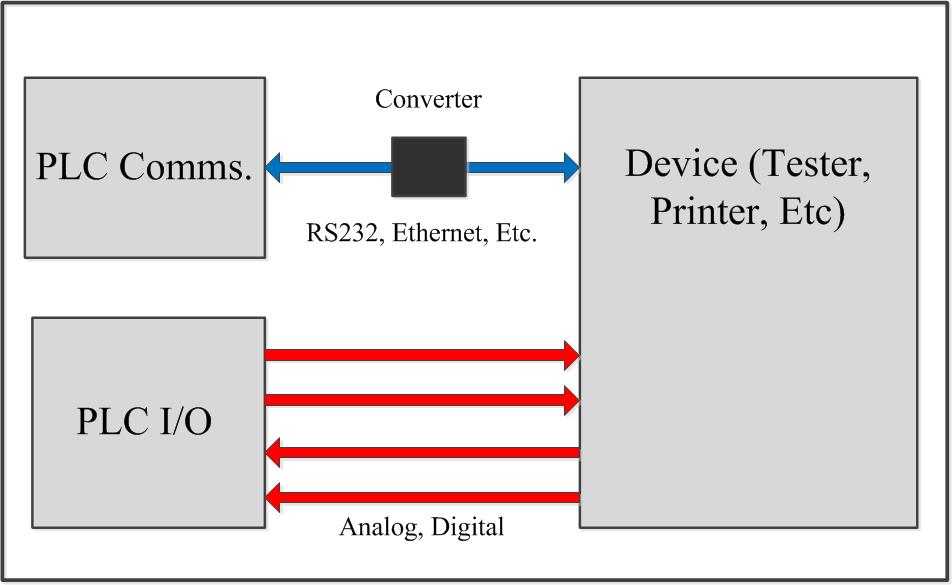
The diagram above shows a typical interface between a PLC and a test device or printer. Many test devices simply need to be triggered using digital I/O and report a pass (OK) or fail (NG) result so that a part can be disposed of properly. If data need to be collected into a PLC or computer for analysis or archiving things can get a bit more complicated. Since the techniques involved apply to printers I will discuss this also.
The first thing to understand about these devices is that they are not necessarily designed to integrate easily with PLCs. Most serial interfaces for devices are tested with a computer and are often meant to interface with the manufacturer’s software. As an afterthought they include the instructions on how to write a computer-based interface for data access and collection, and only then they may consider that the device may have to interface with a PLC. There are exceptions to this, such as Cognex cameras or some other OEM devices that may write instructions for communications over Ethernet/IP, Profibus or DeviceNet. Typically however, the manufacturer will provide a document containing the details of the serial port settings and a list of commands or description of the protocol. This will usually vary from manufacturer to manufacturer; Cosmo will be different from Cincinnati Test, which will be different from Zebra, which will be different from… you get the picture. So the first step in integrating a device over a communications link is to get the manufacturer’s documentation.
Serial communication setup includes selection of the baud rate, handshaking, stop bits, parity and hardware setup. This is in addition to whatever communication protocol is used. A safe bet is that most devices will have a basic ASCII interface of some type that will act very much as a serial printer. This means that the device will send and receive ASCII character strings. ASCII is simply a list of printable and non-printable characters used for data interchange, a table can be found here.
When bringing this data into or sending it out of a PLC serial port, different manufacturers use different methods. Typically a STRING type tag or data register location is defined in the program. This allows the individual characters of the string to be placed in individual locations and manipulated as necessary; this manipulation is known as parsing a string.
An example of a string that could arrive from a device containing test results might look as follows:
“^{STX}TU_1.0,Unit = mPa, CR T1 = 0012.54961, T2 = 0131.73842, R1 = NG, R2 = OK, CR{ETX}”
The desired values are embedded in this string of characters and must be extracted to archive or display data on an HMI. Some of the characters in this string are not even printable, such as the STX (Hex 02), ETX (Hex 03), and Carriage Return (CR, Hex OD). We would certainly not want these included in our display.
There are instructions in most PLC software packages that make searching for characters and stripping values out of strings easier. MID might be a command where one can search for the character number of a particular section, such as the T1 or T2 values shown above. Once this location is known, it might be easy to copy a certain number of characters into another data location to be further refined. For instance, 5 characters after the “T” is the first number of the data value we want to isolate. Perhaps the numerical portion of the string is always 10 characters long (including the decimal point), so the values can be stripped out using simple math.
Other instructions allow the determination of whether the leading or trailing characters are zeroes. This allows their removal also. If the number then needs to be displayed in numerical format rather than ASCII characters (for instance, so you can use the numbers in calculations), there are instructions for ASCII to numerical conversion also.
A device will usually have commands that can be sent to it that will configure parameters, select recipe or program numbers, or trigger the device. Like the strings that are sent from the device, the formatting of the string and commands sent will differ from device to device. I usually take the manufacturer’s documentation and make a spreadsheet with all of the commands and responses along with what they mean. Entries might look like “TRG_CH.1 = Trigger Channel 1” or “{STX} HEX 02 All messages must start with this”. Once this has been done for a particular device I can the archive the document for later access in case I have to do the same interface again someday.
Building output character strings is sometimes known as concatenation. This is where characters are put together to make longer strings; unprintable characters often must be treated specially in this case. For instance, even in this blog post, when I tried to embed my STX and ETX characters inside the <> delimiters as they were in the original string, my WordPress software stripped them out and made them invisible. Obviously these characters still mean something to the software.
Amit, if you are reading this you can see that there really is no simple answer to your question. It has been over ten years since I integrated a Cosmo tester specifically and I am sure their documentation has changed. At that time they also only had serial communications, since then various forms of Ethernet have become much more widespread, especially on the PLC side.
Another note concerning standard serial communications: In the diagram at the top of this page I placed a black box labeled “converter” on the communications arrow. Because there are so many different protocols that are used for both serial and Ethernet-type communications, I often use an intermediate device for conversion; for example Real Time Automation (RTA) makes various converters for different protocols. This can save a lot of time in the integration process, for example, incoming and outgoing strings can be directly mapped into manufacturer-specific data registers and tags, saving a lot of time in conversion or archaic MSG instructions. I recommend RTA highly, their documentation and phone support is excellent.
Feel free to leave a comment or send an e-mail if you have more to say on this subject. This is one of the more complex tasks that is done in systems integration and controls, it is certainly easier to accomplish using a PC and standard programming tools. Sometimes you have to do it with a PLC though, hope this helps!

Electrical Engineer and business owner from the Nashville, Tennessee area. I also play music, Chess and Go.
There are hardly any books on automation technology that adequately spoke on the topic previously. This is what makes your honest work highly important and helpful to readers.
For me, this is truly an excellent resource – it covers almost all concepts on automation and renders them easy to understand too.
Even though your compilation may not offer enough practical knowledge, all scientific and mathematical expressions are clearly explicated. There is not a point where it fails to help the reader hone their theoretical awareness of the concept.
And then practicing things automatically becomes a simple task once you have key information. Great work, especially for those who are about to get started in automation! Thanks so much!