CAD and Wire Numbers
Today’s topic concerns an area that affects engineers, technicians and sometimes even office personnel and yes, management. A major part of building anything involves accurately designing and describing the thing that is to be built. If all of the required information is not present on the design documents major problems can occur, and usually do.
Best case, something may be built incorrectly (not meeting standards), be caught in-house and have to be corrected. This costs money in both time and sometimes, hardware. Worst case, the product may be built in violation of regulations or laws, be shipped to a customer and cause damage to equipment or injury/death to personnel. This of course is much more serious and reinforces how important our decisions and diligence can be. Designers and technicians have a great responsibility to their company, co-workers and customers.
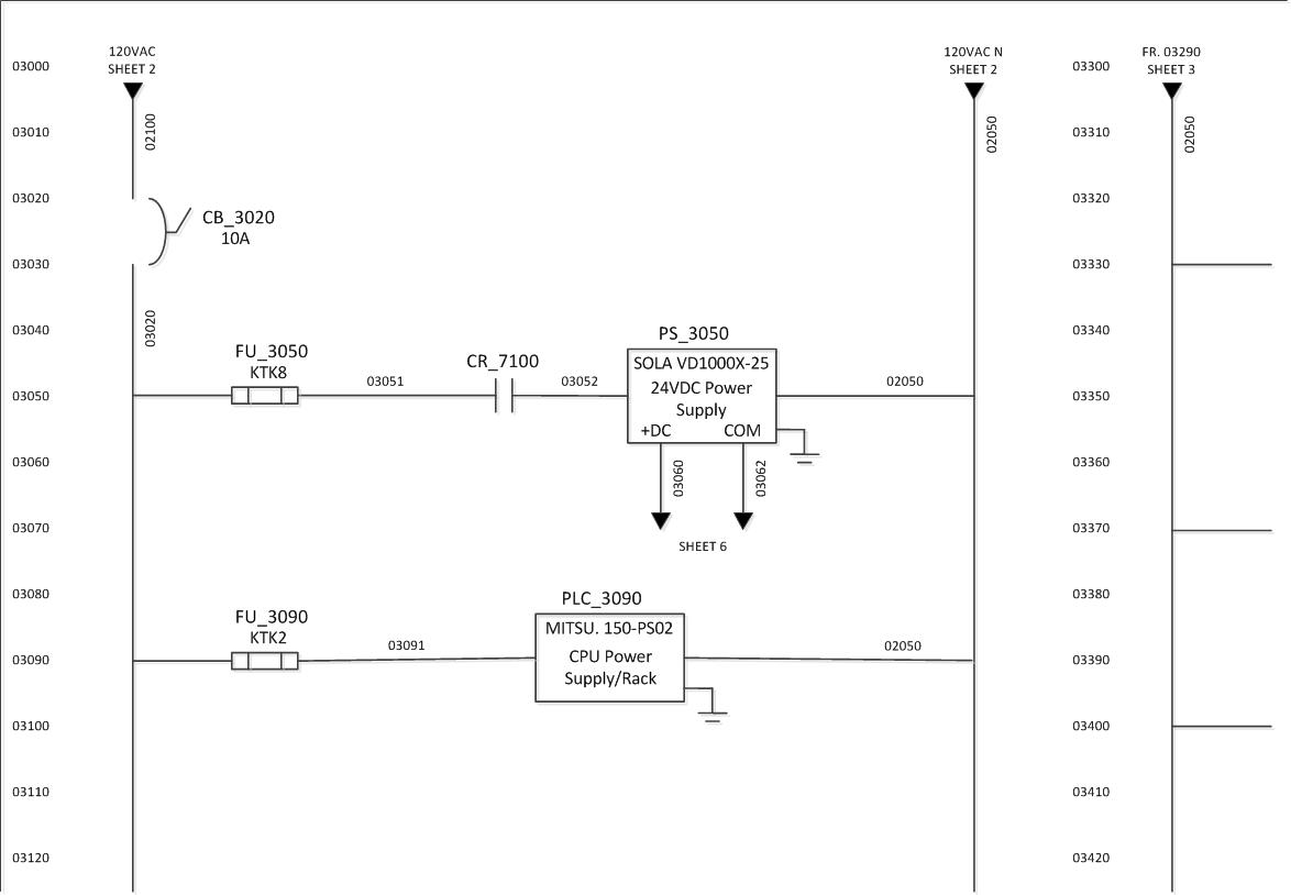
The drawing above is a generic representation of an electrical CAD design. I would like to illustrate several points with this drawing that I feel are important.
In the United States, there are a variety of standards for CAD drawings, but most of the formal ones pertain more to building and architectural wiring than to machine controls. As with many other controls-related issues, Europe is far ahead of the US in establishing a formal set of regulations. The IEC and ISO both have standards associated with electrical controls schematics. Unfortunately, many OEMs in the United States don’t do a very good job of following them.
The first item I would like to talk about is line numbers. These are not just a suggestion; they are mandatory. In the above drawing, I have chosen to use a five-digit line number that increments by tens. The first two digits indicate the sheet number of the drawing set, allowing for a maximum of 99 sheets. When I worked for Wright Industries, I believe we had the capability of generating up to 9999 pages within the drawing set, though I never saw sets of more than a few hundred pages. More sheets usually meant separating the drawings into different sets for different sections of a line or machine. Most OEMs can probably get by with 99 pages or less.
Incrementing by 10 allows for a maximum of 10 wire numbers to be placed on a line. Note the power supply on line 3050. Only two wire numbers have been generated on this line, 3051 and 3052. The line leading to the fuse is 3020 as it is all the way down the left rail. This is because electrically the beginning of all of the branches are the same point. The other two numbers are assigned because if the fuse were to blow or CR_7100 were to be in the off state, the electrical condition of the wire number point would change.
Note the numbers of some of the components on the drawing. CB (Circuit Breaker)3020 is numbered based on where the symbol drawing starts on the rail. CR_7100 (Control Relay) has an entirely different number. Why is this?
The coil of CR_7100 can assume to be located on sheet 7, tenth line from the top. This assumption is easy to make because the other components on this page are numbered that way. The same type of assumption can be made as to the origin of wire numbers 2100 and 2050, both originating on sheet 2. Another assumption about the origin of wire 2100: there is at least a breaker and maybe a transformer between it and the incoming power source. Supply power is often labeled L1 and L2. Since the neutral rail of the drawing is labeled 2050 rather than L2, one might assume that it was created from a transformer tap rather than incoming power.
I have seen many OEM drawings where designers have named wires arbitrarily “1,2,3,4A…”. This tells you nothing about the drawing or electrical system. It is a sign that the company does not have an experienced electrical designer or electrical standards. Other problems I have seen include L1 entering one side of a circuit protection device and emerging on the other side as L3! This is again the sign of a lack of knowledge or standards.
There are a few other helpful pieces of information that are not mandatory on the above drawing. The part number and manufacturer of a couple of components are listed on the sheet. This can be helpful to personnel building or troubleshooting an electrical panel as it may save them from having to flip to the BOM sheet of the drawing set.
Other information that could have been placed on the sheet include other component part numbers or wire color and gauge sizes. If a panel building shop has a standard for wire colors and sizing based on location and ampacity it may not be necessary to label the wire with “THHN Blue #18AWG” or the like, but it is often done anyway.
A quick note on the wiring of I/O points: these wire numbers are often labeled with only the line number from the sheet on which the input or output card is located. I like to also reference the wire or cable with the actual I/O address as a physical label. This allows for easier troubleshooting of the system. There are often engraved tags mounted close to sensors and valves and when cables are disconnected the I/O information allows for mistake-free reconnection without having to refer to the schematics. It is also convenient for the controls engineer to be able to check a sensor status with no schematics.
Schematic drawings are made for several different “customers”: the panel-builder, the controls engineer, the maintenance or assembly personnel and the end-user. To that end it is important to include as much extra information as necessary to make it easier for these customers. It is rare that I have seen too much information on a set of schematics, though that has happened also. Of course contradictory or confusing information is a bad thing. Much of electrical and CAD design can be determined by common sense in addition to adherence to standards.
AutoCAD Electrical can help by automatically generating line and component numbers as well as off-page references, but it can also add time for an inexperienced user. A nice feature of this CAD package is that it accounts for all of your BOM items, making it harder to make an error. It also assists in determining the proper quantities for terminal blocks and panel layout.

Electrical Engineer and business owner from the Nashville, Tennessee area. I also play music, Chess and Go.
That is an excellent overview of electrical schematics. I have been using AutoCAD Electrical for 12 years now as part of my controls engineering responsibilities. Investing time in using the software tools properly pays off in the long term. I do like your treatment of using 5 digit numbers so all the numbering is consistent. However, convincing production / panel building department to generate 5 digit numbers is difficult!
I have also used a technique of using 3 digit numbers for common, non-changing numbers such as power distribution for the various DC and AC control circuits.
The standard of numbering wires you think is arbitrary “1,2,3,4A…” is not. It is the standard for industrial prints in the USA. 1 & 2 are always hot and neutral or L1 L2. The number increments after the wiring goes through a device. For example: L1 wire is numbered 1. if it passes through a fuse or breaker the number is optionally incremented to 3, since L2 is numbered 2, or it remains 1 only for the incoming power. Other than that when ever it passes through anything in the circuit it is incremented by 1. So in a circuit L1 passes through a breaker after coming in, it remains 1. Then a switch is connected to 1, the number becomes 3. Wire 3 is connected to a pilot light, since the other side of the device is connected to L2 the wire number is 2. The numbering starts at the top of the sheet. This is what is taught in school to technicians and incremental. Adding a letter after the number is caused by changes after installation. Instead of renumbering all the numbers in the cabinet after adding a device in line between devices, you connect that device to say wire 4 then number your new wire 4A. In the method you described I have encountered situations where a wire number went from 1051 to 1152 to 2453 even though they were on the same circuit, because they were on different sheets. A technician or installer does not care what sheet a wire is on. Wire 3 is same everywhere. Using the system you described can make it easier to find a wire line on a print, but for a technician it is not important. It is important to a technician to find the device in the print, then the wire numbers connected to the device to find the numbers on the machine.
I would have to differ with you on this. At all large machine builders the page number and line number is the reference for sensor locations, this includes companies like ATS, Wright Industries (now owned by JR Automation) and ATC. These companies build machinery for all of the large automotive manufacturers, Proctor and Gamble, 3M, and medical/pharmaceutical manufacturers. The technicians in these plants are used to this and it has become a de facto standard. I don’t doubt what you are saying that this is taught differently in colleges, and certainly OEMs number their pages as you describe, but that just illustrates what I am saying, that there is no single method in the US. The EU is different. P&IDs are yet another method. I say this as I am in a bottling plant in Florida and am looking at two sets of drawings, one from the EU and one from a US manufacturer, both numbered as I described with page number references.