Anatomy of a Photoeye
One of my first projects when I was in engineering school was to make a coin counter that would detect the size of various coins as they rolled down a ramp and total up the denominations. The circuitry was fairly straightforward; there was a programmable chip that did the math, a series of 7-segment displays to show the total, and a row of photoemitter and photodetector LED pairs arranged so that they would be blocked by the different coins as they rolled down the ramp.
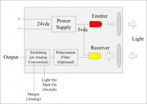
This was my first introduction to photoeyes. I have already discussed the different types of photoeyes in a previous post, the physical arrangement may be different than the above picture. In the case of a through-beam for instance, there would be a power converter inside each of the two units, hence the typically greater cost. For a diffuse reflective sensor the polarization filter would not be needed, this is only required for use with corner-cube type reflectors.
I didn’t mention the margin adjustment in the previous article… this allows a threshold to be set so that small objects or colors might be differentiated when operated as a diffuse sensor. Generally the potentiometer can be maximized if looking for absence/presence. There is also often a margin light on many photoeyes in addition to a light to indicate the state of the output. This allows for maximization of the signal when adjusting the sensor position. A switch for NPN and PNP functionality is also sometimes also present for so-called “universal” photoeyes: most manufacturers choose to simply provide an additional wire for this instead.
The lenses are another feature I wish I had when doing my project… The range for a “naked” LED is very short. Lenses are also useful in narrowing the beam so that light doesn’t diffuse around the detected object. Other parts include the (usually plastic) housing, quick disconnect wiring for cables, and a clear plastic cover for the lens.
For diffuse sensors the output may be analog. This can allow for color or size differentiation. A cool feature I used to sometimes see was a small bargraph on the side of the sensor housing, Tri-tronics had this on their sensors and many fiber optics still have this feature. Another common feature is a “teach” button which is used to learn the difference between signals when an object is present or absent. This would be useful again in a diffuse reflective application but in my opinion it overly complicates setup when used for through beam or retroreflective applications. Manufacturers keep putting them on through beams also though so somebody must like them…
I hope this helps answer some questions you may have had and stops you from ruining a perfectly good eye to figure out “what the heck is in there anyway?”

