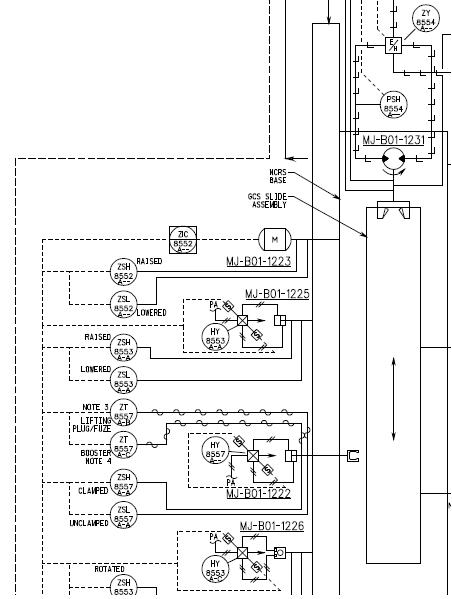
P&ID and Machine Design

The process industry has used P&ID (Piping and Instrumentation Diagrams) for many years as a method of describing the relationships between piping, instrumentation and system components. Usually this is applied to chemical, batching or fluid transfer projects and is nearly unknown in the industrial machinebuilding industry. Larger engineering firms such as Bechtel, Parsons or CH2M Hill however are very dependent on this type of system representation though they don’t deal with production machinery and discrete logic as much.
In my experience dealing with various machine building companies and integrators there is no single drawing or design system that easily allows mechanical and controls designers to exchange conceptual information quickly during the pre-design phase of discussing machines. 3D “cartoons”, timing diagrams and CAD or hand sketches (often on napkins) are exchanged between engineers and then often discarded after the machine design has been firmed up. In my previous controls oriented company we had developed a shorthand of circles, X’s and various letters to depict the mechanical layout and electrical/controls interfacing of a machine. This was usually done on graph paper and used to generate a rough I/O count and name the actuators and stations of the machine before design began. This technique varied from team to team and was never really formalized.
P&ID drawings do not lend themselves as well to discrete machine design. There are hundreds of symbols for flow oriented devices but components such as photoeyes, proximity switches, motor starters and relays are either very generic or not used at all. Determining whether a sensor is a through-beam or retroreflective photoeye or an inductive proximity switch is usually not possible just by looking at the diagram.
Wouldn’t it be nice if there was some kind of common language or set of tools that could be used across disciplines that was appropriate for machinery? I would propose that the P&ID system would be a good starting point as it has a good numbering system, a large set of already developed symbols and widespread use in industry. The only remaining piece of the puzzle that would need to be elaborated upon are the devices described above and some modification of the numbering system. Safety devices such as MCRs and light curtains would need to be represented and a bit more commonality and formalizing of the system would need to take place. Currently the larger engineering companies each have their own slightly different sets of symbols. A software package that incorporates a standard set of symbols and numbering sytem but could be modified to add symbols would be very useful.
If anyone knows of such a software package please let me know. If one doesn’t exist I am interested in collaborating with an enterprising programmer to develop one as a commercial enterprise. It always helps to have the right tools!

I’m not sure I’d use such a system; I suspect it’s usefulness partly depends on the type of machine. My company uses Via Wiring Diagram (now AutoCAD Electrical), and we haven’t received any customer complaints.
As far as I know, there isn’t such software out there. I’d say the most important thing is to get the symbols and process down first, then worry about creating software. In other words, you’re proposing a drawing standard, not a software standard, that can be used by hand, by 2D CAD, and by electrical schematic software.
You could start by making symbols for AutoCAD and compatible software. There are at least 2 excellent quality free AutoCAD clones, DraftSight and DoubleCAD XT.
If you want to go further, and add more schematic specific capability, you can use AutoCAD or (better choice) one of the clones as a base and add custom menus and scripts, just like ECT/Bentley Promis-e and Via/AutoDesk Electrical do. Note that not all 2D programs support add-ins (IIRC, AutoCAD LT doesn’t; DraftSight can, but the add-ins have to be sold via the Graebert app store).
You can also get the backend of a 2D CAD program from the ODA (the Teigha platform); you need to add a user interface (Deelip Menezes wrote a book that shows how to do it).
You’re right about the usefulness depending on the type of machine. When I was first told to generate a P&ID for a discrete machine I was frustrated by the lack of differentiation of symbols for items like photoeyes, grippers, indexers and other components. At the same time there were so many different types of valves and analog devices that it was hard to keep up with.
I am currently using AutoCAD Electrical to generate the required diagrams and it has been pretty easy to create libraries of symbols. Unfortunately our mechanical department rarely uses AutoCAD, being much more dependent on Solidworks. I know our customer uses some kind of P&ID specific program to generate their drawings and then .pdfs them to us for modification.
The more I use these diagrams though the more I realize the lack of a common language for the preliminary design between mechanical and controls departments. With just a few modifications this may be a good starting point since our customer is mandating the P&IDs as the root document for our design information exchange. Thanks for the feedback!
Actually I am working in process automation and I am moving to machinery system. In process P&ID is the base of documentation.
Actually I was looking for diagram similar to P&ID for machinery and I found this page.
AJ